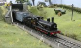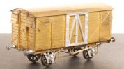
The Heybridge Railway, 1889 to 1913

. . return to model making
  • Richard Gawler

    Western Thunderer
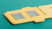
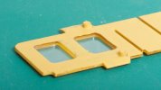
    Richard - what are your thoughts on replacing the View attachment 192757 with View attachment 192758 ?

    It's unfortunate they've moulded them as shallow trays. They would have been better left as solid panes in Roco HO fashion.

    I noted earlier you painted the inside of the glazing to match the interior of the carriage sides - it may be worth painting the outside face of the moulding a brown or mahogany colour including the edges of the panes to see the effect. If you use acrylics this can be taken off by just rubbing with a cotton wool bud if it does not work.

    I have a street car with similar glazing and just knocked up this in 15 minutes (nothing scientific) and photographed under a 60w daylight bulb to see the effect. I think it will be less noticable with 3V dimmed LEDs.

    Car interior

    View attachment 193037

    Car Exterior. I painted in between and the edges of the panes with mahogany, car body colour (Santa Fe red) and a black Sharpie permanent marker.

    View attachment 193036

    And what it looks like inside the car held under the workbench 60w daylight bulb. I think it can be disguised by weathering the panes and cleaning the centres leaving the edges dusty.

    View attachment 193038

    In a 19th century wooden coach, the glazing sits close to the outside of the body and the interior includes a rebate inside the glass. And, in the model, the scale thickness of the glazing is negligible.

    Somewhat inspired by Dave's approach, I have extended the interior colour (yellow ochre straight from the bottle) onto more of the glazing.

    DSC_3982.jpeg
    On the outside of the mouldings I have put paint everywhere except the faces of the window panes.

    DSC_3981.jpeg
    On the inside I have put paint over the whole of the flat vertical surface (but not inside the recesses, this would be too difficult).

    DSC_3975.jpeg
    And this is the result :cool:

    I have used two or three coats of yellow ochre paint everywhere, fairly obviously a primer is not possible. I think this is a worthwhile improvement over the original appearance.
     
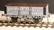
    PO 5-plank wagon 'Brymbo Steel Company'
  • Richard Gawler

    Western Thunderer
    DSC_4173.jpeg
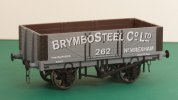
    A PO wagon for specialised steel products ought to benefit the Heybridge Railway, so when a suitably liveried model from Dapol appeared in a small ad here I snapped it up.

    The Brymbo Steel Company wagon is one of several models within Dapol’s 7F-051-nnn series of stock numbers. This series means it has five planks, a timber underframe and a nine-foot wheelbase (all good for the Heybridge Railway), opening doors (good for photography) but sadly a parentage which seems to have been drawn from multiple prototypes, and brake blocks sitting way too far from the wheels.

    I have already bought a sibling to this model and sold it so it seemed best to make the effort to make this second one look a bit better.

    DSC_4137.jpeg
    Much depends on what you know about RCH wagons. If you don’t know very much (like me) then only the brake blocks look really wrong.

    DSC_4146.jpeg
    I cut all of the brake fittings away from one side. My feeling is, this operation cannot really go wrong because I will be happy enough to have a wagon with brakes on only one side.

    I had spare brake parts left over from some Slater’s kits so I glued these into place. The Slater's combined twin brake arm and shoe moulding is too short so I cut it into three pieces and then glued them back together in position on the model. The joints on the brake hangers are reinforced with 1 mm square styrene.

    DSC_4145.jpeg
    The original brakes on the opposite side were useful to hold a piece of wire to align everything while the solvent hardened.

    DSC_4168.jpeg
    The safety loops are brass wire fitted into 0.7 mm holes and fixed with CA glue, and the inner vee hanger is also Slater's. The brake handle and the outer vee hanger are a one-piece moulding from a Three Aitch kit.

    DSC_4161.jpeg
    This effort took barely two hours (not counting taking the photos and writing this post) and I think the result looks a lot better. In fact the wagon now looks plausible if not prototypical. I can cut off the original brake gear on the other side or keep it to show what can be done.

    I do wonder if the Brymbo Steel Company owned these wagons to carry coal for their furnaces rather than steel for their customers. If so then I will best accept “ignorance is bliss” for the purpose of the original wagons as well as the details of this model.
     
    ( Diversion : GER Y14 visits 'Taw Magna', Ilford and West Essex club )
  • Richard Gawler

    Western Thunderer
    My Y14 travelled along the route of GER main line today, though in its transit box and partly along the ‘electric’ (suburban lines) added in LNER days. This was to visit the Ilford and West Essex MRC to enjoy their club open day.

    The club has a rather fabulous 7mm FS layout called ‘Taw Magna’, which seemed to enjoy its model visitor as much as I enjoyed meeting members of the club.

    P1050438.jpeg
    BR train provided by the host.

    P1050451.jpeg
    Somehow, the scenic setting brings the model to life. I cannot achieve this this sort of look on the bare test track at home.

    P1050434.jpeg
    Ignoring the van, I can pretend this is some kind of locomotive exchange and trial.

    P1050446.jpeg
    The Citroen on the bridge brings this view into the realms of preservation . . . I will have to guess, the other road vehicles are preserved as well.

    This is the first time the Y14 has run on a scenic indoor layout. Many people remarked on how well the loco ran and one person expressed disbelief that the chassis is rigid. To be honest, the combination of loco and layout performed impeccably. The trackwork here is first class.

    Thank you to the Ilford and West Essex club for welcoming me and Y14 and letting me do this impromptu running session :)
     
    Manning, Wardle class 'F' (built 1888)
  • Richard Gawler

    Western Thunderer
    DSC_4181.jpeg
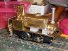
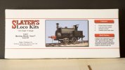
    I bought the kit for the MW class F in November last year, when I felt the Y14 was going to work out okay. I am hoping this kit is a sensible progression for me. It is my first loco with outside cylinders, first with suspension, first with sprung wire pickups, and first with a two-stage gearbox.

    It is also my first brass kit for any coach, wagon or loco not created by Connoisseur Models; and so my first without Jim’s marvellous instructions and a first without the unwritten but frequently re-quoted words, “they go together”. Slater’s have few loco kits on their web site but this one has the year 1985 on its etches, and even the name of the designer too. Their wagon kits are good, so I can be optimistic.
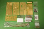
    DSC_4222.jpeg
    There are four etches for the body from 0.4 mm brass, one for the chassis from 0.5 mm brass and one for the side rods from steel. There are alternate parts for different cabs and spectacle plates and one of the etches is devoted to an enclosed cab. The parts are numbered on the etches, which looks good, but I see numbers 1 to 6 at least are used twice, perhaps not so good.
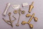
    DSC_4245.jpeg
    The detail castings are of a very good standard so if they fit I should be able to build a good-looking model. I am guessing the metals here are pewter as well as white metal and brass. Nice touches include turned steel buffer heads (though I might take these for my GER van) and plenty of spare half-etched holes to practise embossing rivets. The boiler has been machined as a brass cylinder and will need work to open up space for the motor.

    I have stumbled upon an essay on these locos in MRJ number 6, and gone on to find their magazine project to build the loco from scratch in 4 mm scale. I could never cope with the intricacy in the smaller scale, but in 7 mm I think I have a chance.
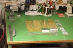
    DSC_4223.jpeg
    The bench is rarely anywhere near this tidy!

    I have made a modest start on the frames but the current September heatwave makes it far too hot to do much more. Hopefully an update next weekend.

    Contents
    1. Lower Firebox and Ashpan (page 47)​
    2. Frames and Attachments for Brakes​
    3. Front Suspension​
    4. Crossheads and Connecting Rods (page 48)​
    5. Gearbox and Motor​
    6. Rear Crankpins​
    7. Front Crankpins​
    8. Cylinders (page 49)​
    9. Front Splashers​
    10. Design Features for Superstructure​
    11. Cab Sides and Coal Bunkers​
    12. Cab Back (page 50)​
    13. Running Plate​
    14. Boiler​
    15. Saddle Tank​
    16. Cab, Brake Standard and Steps​
    17. Springs and Sand Boxes​
    18. Smokebox​
    19. Underpinnings (page 51)​
    20. Clack Valves​
    21. Chimney​
    22. Firebox (page 53)​
    23. Reverser Reach Rod (page 55)​
    24. Motor Mount​
    25. Brake Gear​
    26. Test Running (1): 9V Battery; and Control Decisions​
    27. Battery Bracket (page 56)​
    28. Injector (page 57)​
    29. Choosing the On/Off Switch and a Fuse​
    30. Saddle Tank (completion)​
    31. Test Running (2): Radio Control (page 58)​
    32. Sanding Gear​
    33. Test Running (3): Endurance​
    34. Cab Roof (omitted)​
    35. Dismantling and Snagging​
    36. Battery Charging Connector (page 59)​
     
    Last edited:
    * model of 'Sankey' built by Allen (unpowered) *
  • Allen M

    Western Thunderer
    Hello Richard
    I built one about 3 years ago as Sankey on the Edge Hill Railway (1 of the Colonel Stephens lines).
    The loco as a whole was as the kits but buffers, normal & center dumb, and brakes where changed to suit.
    One point I would advise. The cylinders have two little tags on them which fit through holes on the frames for soldering (gluing) on. I drilled a third hole for a small screw, 10BA or may have been 8BA. This was fixed to the casting before the whole assembly was built. Jus be careful the dead does not catch the piston rod. Everything can now be built & painted the cylinder assemblies attached with (bit of a fiddle) nuts.
    49 - First fit side-front.JPG63 - Side view posed.JPG64 - Three quarter view posed.JPG

    Hope this is of help

    Regards
    Allen
     
    . . design features for superstructure
  • Richard Gawler

    Western Thunderer
    I have started the build by soldering parts together rather than deciding precisely which prototype I want to build. This probably sounds a bit reckless but I will at least try to drill the holes needed for extra fittings while the parts are still flat on their frets.
    . . .

    10. Design Features for Superstructure
    The chassis is built and I cannot put off the decisions for construction of the superstructure any longer.

    I want to build a model of a class F as it might have run from around 1894 to 1913. To do this, I am taking the features of works number 1056 ‘Frederica’ but giving my loco works number 1050 with a fictitious name ‘Heybridge A’ and a new cab. My main reference is an essay on the class by Don Townsley, which appeared in issue number 6 of the Model Railway Journal.

    I want to give my loco the following features:
    • Two sand boxes, one each side between the wheels
    • Buffer beams of timber
    • Two sets of buffers: sprung outer buffers and dumb inner buffers
    • A flat, half-round smokebox door
    • Riveted smoke box
    • Welded saddle tank (no visible rivet heads)
    • Rack for fire irons on top of saddle tank (*)
    • Handrails on saddle tank with two stanchions not three
    • Handrail around chimney fitted to front of saddle tank
    • No cab stays
    • Cab made from a simple spectacle plate with an additional overall roof (*)
    • Cab back to be curved (the straight pattern was (generally!) used later, with factory-fitted enclosed cabs)
    • Five-link couplings (*)
    When I return to the chassis, the brakes will be of the cast iron type, as supplied with the kit.

    I will have to find or make the parts for the three items (*). The other features will be from the kit. Hopefully, there won’t be anything I find too difficult. My only modification to the chassis to accommodate these has been to cut off the mounting points for the front sand pipes.

    The real 1050 was a class F named ‘Drabble’. I don’t have any photographs of this loco and hopefully there won’t be too many out there because it worked for only one owner in Britain before it was exported to South America.
     
    Last edited:
    ( Diversion: 925 and Charlie visit the Middy )
  • Richard Gawler

    Western Thunderer
    Nellie visits the Middy.

    The history of the Heybridge Railway records that Nellie the crane tank was destroyed during the Zepellin raid of the night of 15/16 April 1916. The "might have been" scenario here depicts the arrival of Nellie at Debenham (this was, of course, on the extension of the Middy) and captures the reaction of a passenger waiting at the time.

    View attachment 184498

    View attachment 184499

    View attachment 184500

    View attachment 184502

    Photos by Tony @Osgood

    925 and Charlie visit the Middy

    I have done a bit more "cuckoo modelling" if this is the proper term, this is to say putting my models onto someone else's layouts to take photographs. The Middy opened its line from Haughley to Laxfield in 1904. I have modelled 925 in its pre-1900 condition, so please excuse the mild anachronism here; the location is just right for a Y14.

    DSC_5319.jpeg
    'Debenham' is an 0 gauge layout built by Paul Clarke and now with a new owner. Nellie came here last April.

    DSC_5281.jpeg
    The down freight has stopped just short of the station with a derailed tank wagon. I guess the prospective passenger still has a long wait.

    DSC_5275.jpeg
    The loco has been turned elsewhere and returned along the branch.

    DSC_5260.jpeg
    The wagon on the right here is the work of @Rob Pulham.

    DSC_5214.jpeg
    'Cratfield' is a 7mm scale layout built by the late John Watson and thankfully preserved.

    DSC_5229.jpeg
    An unusual light engine movement photographed on a Sunday. A villager has reported the repeated discharge of a shotgun in nearby Grouse Field, and the Constable has had a quiet word with the crew.

    DSC_5244.jpeg
    Again, the locomotive has turned off-scene, this time before coaling.

    DSC_5304.jpeg
    Finally Charlie and his chauldron wagon. Charlie can't tell the difference between 0 gauge and S7, but please do not look too closely at his harness.
     
    Last edited:
    * model built by Dave (much polished brasswork) *
  • Richard Gawler

    Western Thunderer
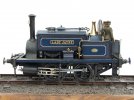
    Two photos of the delightful 'Lady Jayne' by Dave ( @wenlock ) which I am posting here with his permission.

    DSCF6666 - Wenlock.JPG

    DSCF6667 - Wenlock.JPG
    I have found this model, along with those by @Allen M and @Rob R, both helpful and inspiring during my build. The kit provides just one illustration of a completed model, this being the photograph on the lid of the box.

    I will be omitting the wheel washing gear but I do want to work up the sanding gear.

    I might change the name of my own model. At the moment it is 'Heybridge A' but this sounds a bit like a power station. Something like 'Lady Marion' would have the much same number of letters and spaces and would be fun to work into the fictional history of the line.
     
    . . 'Lady Marion', completed model
  • Richard Gawler

    Western Thunderer
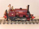
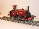
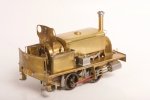
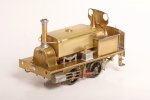
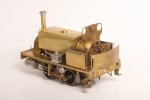
    MW Class F 'Lady Marion', Unpainted

    These are my photos of 'Lady Marion' unpainted, all taken on 10th December which was the day after the test runs at NEEGOG.

    DSC_5604.jpeg

    DSC_5609.jpeg

    DSC_5606.jpeg

    DSC_5614.jpeg

    DSC_5615.jpeg

    DSC_5611.jpeg
    I do think the High Level 'Roadrunner' fitted in well here. It is almost invisible from above. The external trappings of radio control (switch, aerial and charging socket) will be almost impossible to see too.

    This is my third 7mm scale loco. The only 4mm loco I ever built was a Wills body kit for a GWR U1, around 1980. The experience was such I never tried again! I also thought a complete 4mm loco would be too intricate for me, but arguably the size of the class F is comparable to many 4mm models except the frames and wheels are further apart.

    DSC_5750.jpeg

    So, with something here for the GWR folk as well as for the industrial ones,

    I wish everybody at WT a wonderful Christmas and a peaceful, prosperous and above all happy New Year.
     
    'River Pant' (freelance 0-4-0)
  • Richard Gawler

    Western Thunderer
    One of our most favourite paintings (it makes us both smile every time we look at it) is also our smallest, the painting itself being just 3" x 2.75".
    The artist was Brian Cunningham and we acquired it in 1992, believing it to be newly painted.

    Having taken it apart yesterday to clean the mount and glass I studied it further - the locomotive's origin had always been a puzzle and the coaches seemed too short.

    I now wonder if this scene might have been painted in 1892, not 1992 (it merely shows 92), and remounted / reframed a hundred years later before it came our way.

    In which case - could what we are looking at here be an accurate rendition of a Heybridge Railway train?
    Could that really be EH or EE waving at the painter from his recently converted private coach?

    If so, you have some more homework - the train comprises 3 x very short and very early 4 wheel coaches, what are the origins of the locomotive (it must be the Railway's or hired in as it is not a known GER type), there is an overbridge, and the line appears to have been fully signalled (unless this view is of the HR train on the GER branch, but then surely the signal posts would be timber not iron lattice....).


    View attachment 184895

    When I was sketching out the history of the Heybridge and Langford Light Railway, I imagined the railway had three locomotives of its own. These were ‘Blackwater’ (a Manning Wardle K class), ‘Kingfisher’ (a larger but still lightweight 0-6-0T) and ‘River Pant’, an 0-4-0 of unknown origin. Of the other locos I have described in this thread, the MW class F and Nellie the crane tank would have belonged to the foundry of E H Bentall; and the GER Y14 belonged of course to the GER. So it is sensible to now think about a second loco for the railway itself.

    I imagine ‘River Pant’ to have been less than a complete success and to have ended up as a stationary boiler inside the foundry of E H Bentall, but I chanced upon a Starter Loco kit by Connoisseur Models so I am going to try to build her. She would have remained in traffic until the railway acquired 'Kingfisher'.

    DSC_5761.jpeg
    The kit provides one large etch, some detail castings, and minor parts like axle bushes and wire and hardware to complete a model. There is even a driver and fireman, so all I have to find is the wheels and a motor/gearbox. The wheels will be Slater's 7837K "3 ft 2in Kitson Industrial" and these are a scale 4 inches smaller diameter than the 3ft 6in wheels which would build the kit as designed.

    The idea is to build a loco having much the same length and width as the Starter Loco, but about a scale foot shorter top to bottom. This reduction will come about by using smaller wheels (saves 1 mm of height), slimming down the frames (saves 2 mm) and reducing the height of the cab, tanks and smokebox (another 4 mm). So hopefully the loco will look a little less upright, and indeed a little more like the illustration kindly posted by Tony :)

    A Happy New Year to all at WT
     
    A Sample of FB Track
  • Richard Gawler

    Western Thunderer
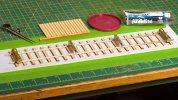
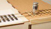
    I have had a go at making some flat bottom track using code 100 rail from Kalgarin and 9 ft sleepers from C&L. This was a trial to find out how much the appearance would differ from Peco’s bullhead flexi track, and to end up with something to stand my Y14 on inside its display case.

    DSC_5977.jpeg
    This is the first time I have used graph paper for years. The sleeper pitch of 7/10ths inch represents a scale 30.5 inches. The code 100 rail is representing 60 to 70 lb/yard prototype.

    The gauge is the wanted 31.5 mm at one end and almost 32 mm at the other end because I made an effort to hold the rails down onto the sleepers but no effort at all to push them sideways against the gauges. I cannot see the difference.

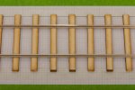
    DSC_5986.jpeg
    I would have rather have no spikes than overscale spikes but I am still searching for something reasonable.

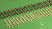
    DSC_5991.jpeg
    So, a marked difference with the flexi track. There isn’t any comparison really.

    Now, I bought the code 100 rail because I thought (and still think) it looks reasonable under a Y14. It is the largest rail section I want for my layout, though I accept it may not really be strong enough for a Y14. Thanks to Col. (@Eastsidepilot) for his recent note on the relaying of the Middy. Hopefully, running at low speeds won't look out of place. I do think, the 2ft 6in sleeper spacing with this rail has a pleasing aesthetic; it looks “light”.

    What I really do need to find out is, how to build this track so I can fix it down onto a baseboard and ballast it without the rails popping off during expansion and contraction. If the layout goes in a car in Winter and the hobby room in Summer then I am looking at a temperature variation of 0 to 30 degrees C.

    Perhaps scale 40 ft lengths would be sensible for the rails. Perhaps, all I need to do is secure the sleepers below the rail joints and ballast using a latex-based glue. Perhaps, it would be best to leave the rails as long as I can and spike them all down. Any guidance here would be very welcome.

    I have put the sample into the display case, it doesn’t photograph very well in there but it looks much better than its predecessor.
     
    Last edited:
    Reference Track including Project Datum
  • Richard Gawler

    Western Thunderer
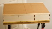
    Ten days on, here is a fresh view of the baseboards to wrap this part of the project up for a while.
    View attachment 188723
    The board from my test track is now the foundation for the new boards. The Kallax underframe is on castors and the baseboard tops have ended up about 1.15 m above the floor. I find this comfortable for using three-links but too high for scenic work. The castors mean there is now room to store the fourth module under the Kallax underframe.

    I have put the wagons here to get a feel for what this scheme can hold. There are four internal, two PO and two foreign. This is about the maximum without getting completely boxed in. The 200 mm headshunt module (in the distance) can hold Nellie and Blackwater (and my next two loco projects) but not Nellie with her tender truck nor (of course) the Y14.

    I suspect the diorama would work better as a "small layout" if the loco spur came from the fiddle yard not the kick-back siding; but will be a better "test track" with the kick-back using the Setrack point. Maybe there is a compromise somewhere in here but my gut feeling is, this is my scenic test piece and test track; and The Layout is for later.

    Last summer I gathered together four baseboard modules to form the basis of my first 7mm layout.

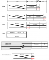
    Basin with modules.png

    Track ‘x’ here will be the datum for the whole project. Primarily, this track defines the relationship between the “main line” of the railway and the pattern maker’s dowels in the ends of the modules. This track also sets up the locations of the tracks behind it, governed by the usual “six foot”. The traverser slides (of course!) so this track also sets the height of all of the other rail heads at all of the baseboard joints.

    DSC_6035.jpeg
    The locations of the baseboard sides are mechanically irrelevant in the scheme but it is nice to have them lined up.

    DSC_6036.jpeg
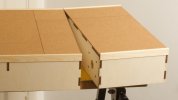
    The joints aren’t too obvious until I open them up.

    I have set the fronts of the pattern maker’s dowels slightly proud of the ends of the modules. Hopefully I can take rails precisely up the ends, and end up with tiny gaps at the joints.

    DSC_6047.jpeg
    The traverser is going to be a project in its own right if I decide it needs some kind of indexing or locking mechanism, because this will need to be within the module not on the top.

    DSC_6044.jpeg
    Above all, the cork gives me enough height to connect to my A6 turnout (build on thick card) without needing to dig downwards into the surface of the diorama module.

    I also have enough height to lay proprietary track on future modules up to the three interchangeable modules. The idea is, nothing gets wasted as the layout evolves.

    DSC_6042.jpeg
    One conclusion from all this is, I think for any modular project it is imperative to build all of the modules yourself. I bought the traverser module secondhand and ready-built (and by mail order) and it has taken much work to bring it up to standard.
     
    Last edited:
    "A first Loco with Radio Control" (GOG Gazette Feb 24)
  • Richard Gawler

    Western Thunderer
    liked your article in the gazette

    Thanks Ken.

    It seems amazing looking back, that this article took most of ten months in all from proposal to publication. This all began with an approach to Philip Willis, the editor of the Gazette last April, followed by a draft article in July. The draft included the photos on the garden railway but I was lacking a photo of the loco in a scenic setting.

    I eventually managed to provide two - one at Taw Magna (courtesy of the Ilford and West Essex club) and one at Debenham (courtesy of a member of WT). The first became the title photo but the second was omitted.

    DSC_5267 full.jpeg
    This is the lost photo from Debenham.

    Of course, by the time I submitted these extra photos I had completely forgotten about the sentence, "I have the cab side plates on order and I expect I will add these next". Oh well.

    I am still pleased with this model. It looks "right" to me, though the lack of a boiler backhead and crew is going to limit the angles for photography for some time ;)
     
    MR fitted van Diagram 360 (1899)
  • Richard Gawler

    Western Thunderer
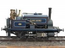
    One of my ideas behind the Heybridge Railway is to show how freight vehicles evolved during my chosen period 1889 to 1913. I sold my GWR Hydra because it didn't quite fit with the look I want for the project, and this left me without a fitted wagon. So I succumbed quite easily to buy this example from the Midland Railway.

    DSC_6120.jpeg
    Rocking axle at one end. Perhaps the plain sheet floor is a substitute for an original kit part.

    DSC_6118.jpeg
    I suspect the door handle has dropped and would be better re-fitted horizontally. The vacuum hoses have been made from a flexible material, perhaps insulation from electrical wire closely-wound springs and are very flexible.

    The wagon is "to carry 5 tons Passenger Trains and 8 tons Goods Trains".
     
    Last edited:
    GER 10 ton van (1910) - buffers and completion
  • Richard Gawler

    Western Thunderer
    DSC_3869.jpeg

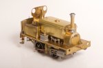
    So this is how the model will look for a while, posed here between my Peco/Parkside NB van and my Three Aitch MR van. I have built this GER van entirely from the kit, except for the copper wire between the brake hangers (I had to destroy the piece supplied in the kit during a rebuild of the brake gear) and of course the Slater's wheels.

    Six months after I first put my GER 10 ton van onto the track I have tracked down some suitable buffers.

    DSC_6222.jpeg
    These are GER wagon buffers from Haywood Railway. They are an upgrade from the cast white metal ones supplied in the kit, and I think worthwhile.

    The axlebox further from the camera is filled flush with epoxy glue but this dries clear. This model is probably structurally complete and ready for painting now.
     
    Rebalancing the Wagon Fleet New
  • Richard Gawler

    Western Thunderer
    Isn’t Brymbo a bit out of area for your railway?

    The balance will get better as I build more wagons for businesses in Essex and neighbouring counties.

    I have done a little re-balancing of my wagon fleet. The Brymbo wagon jars in my mind. I am pleased with the brake gear but somehow, the combination of unprotypical model and distant operator seems that bit too wrong. I would probably keep it if it was a better model or a more local owner. At least I know what I did to the brakes, the photos are on WT, and I could do similar rebuilds to different models.

    I said goodbye to my GWR Hydra a while ago. This was a scale model and suitable but I couldn't devise a sensible load for it to bring to the Heybridge Railway. So I suppose I am doing fairly well if I have built 14 wagons and only let go of one.

    I bought some 9ft sleepers from a modeller in Devon and discovered he wanted to downsize his GER collection. So I could hardly resist these . . .

    DSC_6512.jpeg

    DSC_6508.jpeg
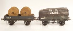
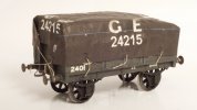
    According to Tatlow (LNER wagons vol.1 p.188), the GER built 3,000 four- and later five-plank wagons to diagram 16 during the decade to 1895. So this model fits my the layout perfectly. I have a Mystery Load too, if I try using playing cards for operations.

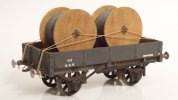
    DSC_6509.jpeg
    I don't know about the drop side wagon yet. Studying Tatlow, it looks as though these didn't make it into the LNER. But drums of electric cable could be making their way to Bentall's factory or, via the navigation to Chelmsford.

    The GER painted these wagons slate grey and this is usefully different to the greys of the wagons belonging to the Heybridge Railway. Thank you Peter.

    As far as rebalancing goes, I now have three GWR wagons instead of four, and three GER wagons instead of one, and I have gained two absolutely beautiful models to do this. Good.
     
    Standards for Building Plain Track New
  • Richard Gawler

    Western Thunderer
    I have had a go at making some flat bottom track using code 100 rail from Kalgarin and 9 ft sleepers from C&L. This was a trial to find out how much the appearance would differ from Peco’s bullhead flexi track, and to end up with something to stand my Y14 on inside its display case.

    View attachment 207552
    This is the first time I have used graph paper for years. The sleeper pitch of 7/10ths inch represents a scale 30.5 inches. The code 100 rail is representing 60 to 70 lb/yard prototype.

    The gauge is the wanted 31.5 mm at one end and almost 32 mm at the other end because I made an effort to hold the rails down onto the sleepers but no effort at all to push them sideways against the gauges. I cannot see the difference.

    View attachment 207553
    I would have rather have no spikes than overscale spikes but I am still searching for something reasonable.

    View attachment 207551
    So, a marked difference with the flexi track. There isn’t any comparison really.

    Now, I bought the code 100 rail because I thought (and still think) it looks reasonable under a Y14. It is the largest rail section I want for my layout, though I accept it may not really be strong enough for a Y14. Thanks to Col. (@Eastsidepilot) for his recent note on the relaying of the Middy. Hopefully, running at low speeds won't look out of place. I do think, the 2ft 6in sleeper spacing with this rail has a pleasing aesthetic; it looks “light”.

    What I really do need to find out is, how to build this track so I can fix it down onto a baseboard and ballast it without the rails popping off during expansion and contraction. If the layout goes in a car in Winter and the hobby room in Summer then I am looking at a temperature variation of 0 to 30 degrees C.

    Perhaps scale 40 ft lengths would be sensible for the rails. Perhaps, all I need to do is secure the sleepers below the rail joints and ballast using a latex-based glue. Perhaps, it would be best to leave the rails as long as I can and spike them all down. Any guidance here would be very welcome.

    I have put the sample into the display case, it doesn’t photograph very well in there but it looks much better than its predecessor.

    Michael thank you so much for all these notes.

    I have just found out (from Four Types of Rail Spikes), a modern spike is 16 mm thick. This equates to 15 thou in 7mm scale, while my 26/6 staples measure 18 x 16 thou. So I will stay with these. I have a household stock of several thousand.

    I have two BH turnouts for my first diorama, so if I use these then I need to build only plain track to begin with. This is for the traverser and its headshunt. I have limited space for a layout, so I want to make the fiddle yard look as nice as I can. Maybe, even good enough for model photography.

    We discussed spiked track earlier; these two posts mark the start and the end of the posts.

    I now have a copy of Peter Paye's book, "The Mid-Suffolk Light Railway" (Wild Swan 1986, reprinted 2003) and this work contains many photographs of the original track at the Middy. Now, I know that these photographs were not taken to record the way all of this track was laid; nor were they taken for the railway modeller. But they do repeatedly show one spike not two on each side of the rails, and rail joints on top of sleepers.

    The photograph of Mendlesham Station posted by @Rob R is annoyingly clearer than many photos in Paye's book, but I am still wanting to think, the use of a second spike seen here was done to reinforce things or to realign them, and not as a routine practice. The additional spikes seem to be dotted around without any clear pattern.

    The Middy was laid with 56 lb/yard rail and I am using code 100 rail which can represent 60 to 70 lb rail. I could claim my rail represents 56 lb/yard rail and this was a (fictional) precursor to the standard adopted by the Middy; but it is easier to leave this one open for now. After all, the Heybridge Railway does see a GER Y14, which would want a heavier rail to reduce the likelihood of breakages.

    The photographs in Paye's book suggest a spacing of about 20 inches between sleepers; a sleeper is 10 inches wide so the pitch would be 30 inches. This is the spacing I chose for my example track on "Heybridge Basin", because I thought it looked about right.

    So . . . I can go for one spike on each side of the rail on each sleeper for the Heybridge Railway. The Board of Trade may well have been unhappy about this, but if so it is easier to write a fictional letter from them to the railway than to double my workload for building the track. The sleeper pitch can stay at 17 to 18 mm (30 inches), and the rail will be code 100.

    Or, to put things more succinctly, "my railway my rules"!

    I am happier to firm up on things like this because I now know what I need to do for rest of the track. The only big unknown remaining is what the pointwork should look like, and I don't need to know this until after I build the fiddle yard, complete the Heybridge Basin project, and start thinking about a layout for Heybridge itself.
     
    Sleeper-built buffer stop (1) construction New
  • Richard Gawler

    Western Thunderer
    I haven't finished a model since the build of the Slater's MW F class last year so it seems like a good idea to try something straightforward and follow it through to completion all in one go. I have plenty of sleepers now so I have made the buffer stop for the goods yard at Heybridge Basin.

    DSC_6528.jpeg
    Sleepers glued onto 1.5 mm mount board. One sloping side here needed a mirror image and had to be re-done.

    DSC_6530.jpeg
    The model is fairly square, but not spot-on.

    DSC_6536.jpeg
    The important thing for me is to make something sufficiently uneven to look as though it was build by people not a laser, but not with so much slack it looks sloppy.

    DSC_6534.jpeg
    This is my first attempt at a "robust" scenic model in 7 mm scale. I hope this is good enough but if others have seen similar structures fail in a rough shunt then do say.

    DSC_6541.jpeg
    Posed at Heybridge Basin.

    Sometimes it is quite satisfying to see a rapid result. This model only took one evening, plus a few minutes the next day to fit the top and arrange the carboard packing underneath. Painting can follow after I have built a few more scenic items.
     
    Last edited:
    Yard crane New
  • Richard Gawler

    Western Thunderer
    I can see two ways to continue this workbench thread. I can either try to paint the buffer stop (and each successive model) or just carry on with the building. I’m not very good at painting (might improve!) and I am waiting for warmer weather to spray primer outdoors, so I will carry on with the building . . .

    Rewind to last January:

    I am building the Peco yard crane in 7mm scale. Their p/n LK-735.

    View attachment 207232

    View attachment 207233
    Please, do we know whether this is a model of a real crane, or perhaps an amalgamation of a few different prototypes? Then I could tweak the model before painting it. Searches are (unsuprisingly) bringing me only adverts for the kit.

    The yard crane for Heybridge Basin is from the Peco kit. I have shortened the jib a bit so the model looks better in the scene, not for any prototypical reason.

    DSC_6543.jpeg
    I have based the jib on a crane preserved at Ellesmere Wharf on the Shropshire Union Canal. The steel girders provided for the jib in the kit are wrapped up inside the white styrene to represent a timber beam.

    DSC_6547.jpeg
    I have added a brass spindle to attach the two stays. This arrangement seems to be more common than fixing the stays to the frame holding the pulley, as portrayed in the kit.

    DSC_6545.jpeg
    The rollers for the chain are brass wire, tube and 14 BA washers.

    DSC_6546.jpeg
    This all comes apart for painting.

    I have picked up a particularly stupid habit of dipping the brush for Plastic Weld into the bottle of phosphoric acid flux, this being followed by pondering why the plastic joint has fallen apart. Also the brush carries contamination onto the model, hence the stains on the jib. Hopefully the primer will still stick :rolleyes:
     
    Top