The Heybridge Railway, 1889 to 1913

Richard Gawler

Western Thunderer
Apart from deliberately using solder as a filler, I am trying to use the GER van to get my soldering under more control and up to a better standard. I now have a few techniques for soldering parts together, and I am getting better at choosing the right way for the parts to hand. I am also trying to do the soldering without leaving myself quite so much tidying up to do.
DSC_3631.jpeg
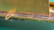
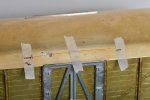
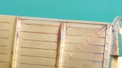
If I had done these horizontal strips below the roof a year ago I would have probably tried to solder them throughout their lengths. Now they are tacked in the three places where they touch, much neater and far less solder.

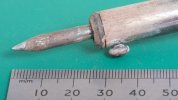
I am assembling all of the brass parts using 188 degree solder, this usually worked with a 40 watt iron and sometimes tidied up with my microflame torch. The iron is an ex-Weller design marketed by CK and bought from Screwfix. I bought a conical bit for it and I use this bit for all of my work on brass. I get on with this bit, the shape makes it easy to get two points of contact in internal corners and the smallish size near the tip doesn't trail huge amounts of unwanted tinning around the work. The torch is useful because it doesn't physically touch the parts. I still overheat things in places, and this brings a reddish residue of copper to the surface. The glass fibre pencil is very good at restoring the colour to make the photos look better, though experience tells me the primer doesn't mind the colour of the brass.
DSC_3644.jpeg
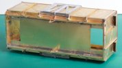
I have given the model a floor from 0.3 mm brass to hold the model square. This is also sturdy enough to let me twist the two long sides relative to each other and persuade them to line up with each other and stay put. I haven't decided how to fix the roof but I would like it to be detachable, this would make painting and any repairs easier.
 
Last edited:

magmouse

Active Member
It’s interesting to read how your tips on soldering and how you are developing your technique. I’m going through the same process with a GWR horsebox, from an old D&S kit. I’m preparing for my first loco build, and want my soldering to be up to scratch, so thanks for sharing - I’m greatly enjoying this thread.

Nick.
 

adrian

Flying Squad
I am assembling all of the brass parts using 188 degree solder, this usually worked with a 40 watt iron and sometimes tidied up with my microflame torch. The iron is an ex-Weller design marketed by CK and bought from Screwfix. I bought a conical bit for it and I use this bit for all of my work on brass. I get on with this bit, the shape makes it easy to get two points of contact in internal corners and the smallish size near the tip doesn't trail huge amounts of unwanted tinning around the work.
To get a joint like that on brass is good going with a 40W iron. Personally I would have used a larger iron from the inside of the van, the thing is solder will always gravitate to the hottest part and by heating from the back, i.e. inside the van then it will draw the solder into the joint.
 

Richard Gawler

Western Thunderer
DSC_3655.jpeg
This is the conical bit in my 40W iron as I left it last week. For bigger joints on heavier pieces of metal (like valances below running plates) I use more length of the tip.

DSC_3647.jpeg
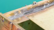
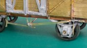
I haven't done anything to the wagon since I took the last photos so here are some closer views of the joint @adrian has noticed. Much of the tinning here is left over from attaching the solebar first. To be honest, it didn't occur to me to try to solder the floor from the inside of the body, because there is a much wider angle of attack from underneath.

DSC_3652.jpeg
The solder hasn't flowed throughout the floor/side contact area - I know this from the quantity of solder I used. But the solder has penetrated a fair way. The pinkish marks here are where I reflowed the solder using the torch. I think most of the flow of the solder here has been created by the flux and capilliary action.

DSC_3656.jpeg
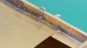
This gap on the opposite side of the model was not part of the plan, but the lack of solder here did give me the flexibility to adjust the vertical twist on the model.

I suggest, we can view this gap as shoddiness or necessity, depending on how good we are at getting four sides of a van together square in two orthogonal planes. I expect the gap will disappear under more solder when the axleguard casting goes on :cool:
 
Last edited:

Richard Gawler

Western Thunderer
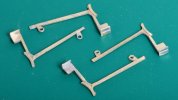
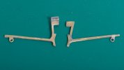
The parts for the brake shoes and their push rods come in pairs and I have put these together with 188 degree solder paint.

DSC_3738.jpeg
It has taken me a while to work out how to best use the paint. I am now applying it to one part with a wooden cocktail stick, clamping the parts together with forceps and a crocodile clip, and running the iron along each edge. This seems to work and there is little cleaning up to do afterwards. The iron draws the molten solder out to the edges so it is easy to see the joint going together. I still used ordinary solder wire to reinforce the internal corners. I removed the cusp from these parts after assembling them together, I think this is easier.
 

Richard Gawler

Western Thunderer
View attachment 164256
I tacked the axle guards in with 145 solder and then set them in Araldite. The first three are easy enough of course. In spite of a special effort with the fourth one, the wagon still has a diagonal rock on its wheels. This is about four but not five thicknesses of budget kitchen baking foil so about 4 thou. Arguably, only I can "see" it - the wagon runs fine.

This build is getting difficult. I want to think I am making the transition from “beginner” to “mildly experienced”, but the underframe is taking me two steps backwards for every step I manage to make forwards. Part of my trouble is not reading the instructions properly (“because I have read the same thing before”) and part is a lack of ability. I wouldn’t want anyone to think the kit is inadequate or defective.

DSC_3745.jpeg
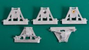
The castings for the axleboxes with their W irons photographed in their supplied state (bottom right), cleaned up, drilled and counter-bored, and with a Slater’s bearing. Two castings received a chamfer to let them fit snugly behind the backs of the horse hooks.

DSC_3766.jpeg
The instructions suggest tacking the brake gear into place and using this to align the wheels. My brake gear didn’t line up very well, probably because my floor is in the way, so I ignored this advice and went my own sweet way. This is proving even more difficult . . .

DSC_3800.jpeg
I attached two castings to line up with the bump stops. So far so good. Using solder to do this is a step forwards from my tender truck where I used epoxy glue, but the choice of technique is all to do with ability.

DSC_3796.jpeg
On the other side of the model, the springs would not line up with the bump stops. I removed the stops, which did not survive the process, and tried adding a fresh one. The kit gives you four spares. But the new one did not line up either, so I am now building a van with bump stops on only one side. I know the sides are square, but the etched rebates to hold the bump stops are not opposite each other, so my error must be in how I have fitted the solebars. It is a bit late to be taking them out so I have added the two remaining castings to set the axles parallel and at right angles to the solebars.

DSC_3808.jpeg
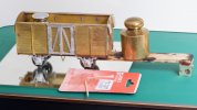
I drilled right through one axlebox oversize and secured its bearing with epoxy glue. The mirror tile is flat, the weight inside the van is holding the first pair of wheels flat on the mirror and the weight on the strip of ply is doing likewise for the second pair while the glue sets.

DSC_3815.jpeg
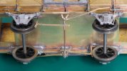
I now have a free-running model which sits flat on the track, and a task and a half ahead to install the brake gear.

At the end of the day, the wheels are functional while the brakes are cosmetic, so this is probably the right priorities for me . . . but the brakes are going to be tricky. Fortunately there is only one to go onto each side, I made up twice as many as I needed.
 

simond

Western Thunderer
Richard,

looking very tidy.

a little bit of plastic rod can soon be carved into a bump stop, and glued in place before paint.

After paint, even you will have to look twice to know which is design and which is ”adjustment”.

(and I wholly agree with your priorities!)

Atb
Simon
 

Lyndhurstman

Western Thunderer
This build is getting difficult. I want to think I am making the transition from “beginner” to “mildly experienced”, but the underframe is taking me two steps backwards for every step I manage to make forwards. Part of my trouble is not reading the instructions properly (“because I have read the same thing before”) and part is a lack of ability. I wouldn’t want anyone to think the kit is inadequate or defective.

View attachment 192216
The castings for the axleboxes with their W irons photographed in their supplied state (bottom right), cleaned up, drilled and counter-bored, and with a Slater’s bearing. Two castings received a chamfer to let them fit snugly behind the backs of the horse hooks.

View attachment 192217
The instructions suggest tacking the brake gear into place and using this to align the wheels. My brake gear didn’t line up very well, probably because my floor is in the way, so I ignored this advice and went my own sweet way. This is proving even more difficult . . .

View attachment 192219
I attached two castings to line up with the bump stops. So far so good. Using solder to do this is a step forwards from my tender truck where I used epoxy glue, but the choice of technique is all to do with ability.

View attachment 192218
On the other side of the model, the springs would not line up with the bump stops. I removed the stops, which did not survive the process, and tried adding a fresh one. The kit gives you four spares. But the new one did not line up either, so I am now building a van with bump stops on only one side. I know the sides are square, but the etched rebates to hold the bump stops are not opposite each other, so my error must be in how I have fitted the solebars. It is a bit late to be taking them out so I have added the two remaining castings to set the axles parallel and at right angles to the solebars.

View attachment 192220
I drilled right through one axlebox oversize and secured its bearing with epoxy glue. The mirror tile is flat, the weight inside the van is holding the first pair of wheels flat on the mirror and the weight on the strip of ply is doing likewise for the second pair while the glue sets.

View attachment 192221
I now have a free-running model which sits flat on the track, and a task and a half ahead to install the brake gear.

At the end of the day, the wheels are functional while the brakes are cosmetic, so this is probably the right priorities for me . . . but the brakes are going to be tricky. Fortunately there is only one to go onto each side, I made up twice as many as I needed.
Hello @Richard Gawler
Nice work.
I had a similar problem with my Connoisseur bolster wagons. In the end, I made up a jig out of plasticard for the axle spacings, and used that to define where the W irons went. Then I fitted the bump stops to suit.

Cheers

Jan
 

Richard Gawler

Western Thunderer
My problem has come about because I ignored the rebates for the bump stops when I fitted the solebars. The solebars are identical (they are from two copies of the same etch) and the rebates are perfectly symmetrical too.

DSC_3824.jpeg
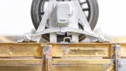
The solebars are slightly too short. For the one at the top in this photo, I set one end hard against the headstock (top left) and shimmed the gap with 0.5 mm brass (top right). For the one at the bottom, I shimmed both ends with 0.3 mm wire. "Because this seemed best at the time".

This gave me an error of about 0.3 mm. I know I claim to have built the sides square, but suppose these are another 0.3 mm out of true as well, measured on the diagonals. Add in getting the axleguards a tiny bit offset as well and I have the error of 0.7 mm or so which prompted me to discard the two bump stops.

Jan, I will remember a jig next time.

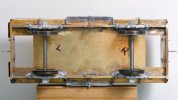
The L and R marks are here because the brake gear is becoming handed as I tease it into place.
 

Richard Gawler

Western Thunderer
DSC_3811.jpeg
I shortened the brake hangers so the shoes line up with the wheels. At least part of this alteration is to make allowance for the floor, which isn’t part of the kit.

The design of the GER brake gear is new to me, and it took me a while to figure out how to build it. I struggled on for a few hours doing it wrong, wrote to Jim McGeown and he sent me some photographs of his own model. The penny then finally dropped.

DSC_3834.jpeg
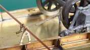
One side of these wagons carried a vee hanger with a reversing mechanism.

DSC_3849.jpeg
The other side carried a vee hanger of the more familiar design.

There is one brake on each side of the van. One side has the operating arm below the brake rod, and the other side has its operating arm above the brake rod. Now these are the right way round, I can comprehend how the brake mechanism worked.

Big sigh of relief.

DSC_3842.jpeg
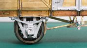
I am very pleased with the clearance between this brake block and its wheel.

DSC_3844.jpeg
The other side isn't quite as good but the brake block is in front of the wheel flange so there isn't any daylight showing through.

Most of these brake parts are there for the third time of fitting and I will stop now while I am ahead :)
 
Last edited:

Richard Gawler

Western Thunderer
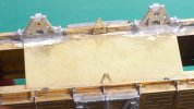
The roof is a rectangle of brass and supplied pre-rolled. I filed shallow rebates into the sides to let it fit over the door castings. There is nothing inside the body I need to get at, so I soldered the roof into place at its two ends.

DSC_3853.jpeg
This is how I marked out the roof for fixing the rain strips and then held the strip before tacking it into place.

DSC_3859.jpeg
I used 145 degree solder to fix the rain strips, partly because they are unlikely to break off and partly because I am joining such dissimilar sized pieces of brass. This is the only 145 solder in the model, all of the rest is 188 for the brass and 100 for the castings.

The GER fitted some of these vans with a vacuum brake and gave them a more interesting livery with red ends, so I will leave off the coupling links until I decide whether to try for one of these. I want to fit some steel buffer heads in place of the cast ones from the kit, so the buffers can go on after I find these.

I have omitted the doorstops because I cannot see them properly. I think for me it is best to leave them off rather than add them crooked or out of line.

I followed up the suggestion of @simond and had a go at adding a missing bump stop from styrene. I could barely put it in the right place and the CA glue was not going to hold so I gave up. To be honest, I can barely see the two I have managed to fit except in photographs. I am starting to think a "small part" for me is one where the longest dimension is less than 2 mm, and such parts are best ignored. They are easier when there is a peg or a rebate or some other mechanical thing to locate them.

DSC_3869.jpeg
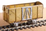
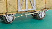
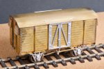
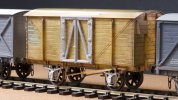
So this is how the model will look for a while, posed here between my Peco/Parkside NB van and my Three Aitch MR van. I have built this GER van entirely from the kit, except for the copper wire between the brake hangers (I had to destroy the piece supplied in the kit during a rebuild of the brake gear) and of course the Slater's wheels.

DSC_3874.jpeg
:drool:

Edit - postscript:

I forgot to mention, the GER built these vans from 1910 onwards, so a bit late for my Heybridge Railway project. Fortunately, they built some almost identical vans, 3 inches shorter, from 1903. The two versions are difficult to tell apart, so my model represents one of the earlier versions for me.
 
Last edited:
Four-wheel saloon part 3

Richard Gawler

Western Thunderer
Final details before painting.

View attachment 184784
The door handles, buffers, coupling hook and vacuum pipes are all from the kit.

I used the lathe to bore the holes in the buffer stocks, and to dress the buffer heads. I tried to double up the door handles to make them look a bit more robust but I dropped the first pair onto the carpet. Even with only four doors to equip I could see I was going to run out of handles so these are single thickness parts from the kit.

View attachment 184783
The buffer heads are resting loose here for the photograph. The castings for the axleboxes and springs are neat and well-made but I will leave these off for now. So I can remove the wheels and their axles during painting.

View attachment 184785
'Blackwater' doesn't have a train brake and the van is unfitted too, but I can see the sort of look I want for my railway in here.

Back to the four-wheel coach, I have had a rethink on leaving off the axleguards. The idea was to make painting easier but really it will make painting harder because fixing them later with solder will ruin the paint and any attempt with glue has a fair to good chance of making a mess. So I have soldered the axleguards into place.

DSC_3886 (2).jpeg

DSC_3888 (2).jpeg
Really this post is an excercise in photography rather than model making but I hope I can be excused because I want to build another coach (a brake composite) before painting this one. Also I am very pleased with this model. The buffer heads are loose for the photographs.

The background here is glossy white paper which was the cover of a A2 size pad of paper. The surface is covered in tiny marks from taking photos but they don't show up.
 
Last edited:
Four-wheel brake coach (1870s on)

Richard Gawler

Western Thunderer
I have succumbed to a Dapol Stroudley coach. The layout will be a whole lot easier to operate if I have a brake coach, this will let me keep the break van for freight trains. The private brake composite won’t really be suitable for this (and I don’t feel ready to build this yet) and I want a second coach to help me to visualise the look of the diorama of Heybridge Basin. And there were only two left in stock at Hattons, so it was pretty much now or never.

This model is really a factory-built and pre-painted kit, and one where the assembly work has used minimal amounts of solvent and glue I guess for speed and efficiency. So dismantling is easy, sometimes a bit too easy but if bits fall off now I have a chance of fixing them back better . . .

DSC_3907.jpeg
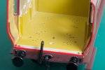
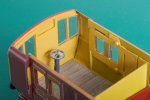
The guard’s compartment is rather visible (through the windows!!) and the floor moulding is covered in holes to let it this part build into different models.

DSC_3926.jpeg
I have covered the floor with some 1:48 scale dolls house flooring paper. Years ago I assembled an engineering log book using a very thin double-sided sticky tape to hold lots of paper notes and sketches. This book is still as good as when I made it so I have used this sort of tape to hold the flooring paper. The brake wheel and its column are castings left over from the Y14.

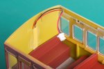
The inside end of this compartment arrived bright red like the outside. I have repainted this using Vallejo ‘Yellow Ochre’. This is a remarkably good match for the factory colour on other inside parts, it is not perfect but I cannot tell the difference looking in through the windows. The coverage over grey primer is very good for a yellow.

DSC_3931.jpeg
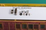
I bought the version of the coach with a light bar and DCC lighting. I have put a strip of styrene over the lighting wires running up the other end of the body, again not perfect but it looks better.

The success in the guards compartment encouraged me to paint the borders of the glazing mouldings to match. I think this takes away the worst of the “one-piece moulded look” on the inside. The design of this model is clever, it uses the same glazing moulding for both sides.

DSC_3936.jpeg
There are two oil lamps for the three passenger compartments. One is located directly above the backs of two seats, but the other was offset by about 4 mm. I don’t know if this is correct for the prototype but somehow it looked wrong so I have moved it. This sort of operation is one where the low coverage of the factory solvent helps a lot, the details pry off with a scalpel.

DSC_3932.jpeg
I took out the decoder and put in a blanking plug and the lighting effect is still the same when running on analogue DC. The lights come on at a low controller setting and stay on at the same brightness.

DSC_3946.jpeg
I realise this still looks very much like it did out of the box, but it did all go back together :)

I want to completely rework the lighting so there are three LEDs in line with the three oil lamps and not four LEDs spread along the coach. If anyone knows the circuit for a constant-brightness lighting circuit please do say. Maybe I could extend the circuit into the saloon and keep the two coaches coupled together. The inner end of the Dapol coach even has a close coupling cam under the floor.
 
Last edited:

Richard Gawler

Western Thunderer
A fair point, and most eloquently made!

I have lots of thoughts, most too hare-brained to record here. Some laser-cut glazing panels might look very good indeed, but only if they come to rest at a consistent depth behind the fronts of the coach sides. I met the proprietor of Shawplan (4mm replacement glazing) some years ago and he explained how some RTR coaches need multiple sizes of panels to accomodate tiny variations in the sizes of the openings.

I have had a go at trimming the moulding I cut out from one of the guard's droplights, but the result is too small and it falls through its opening.

At the moment, I am very happy with this model, and happy with the saloon as well. I won't be completely happy with runnning the two together, but such is life. I ought to accept, I cannot run much of anything at all until I have some kind of a layout, so I suspect my priorities ought to be focused there . . . but I am rather enjoying making rolling stock. So - I will accept the model for what it is for the time being.
 
Last edited:
Richard Gawler

Western Thunderer
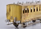
Thinking a tiny bit more, only I can say what the trains on my might have been railway looked like. The only boundaries are those of historical believability hence oil not gas lighting. Supposing the railway started it's operations with a brake third coach, the coach could look like this Dapol one. When the railway acquired its saloon a few years later, the brake coach might have morphed into something different, like a brass model. No one can say either is wrong. I can have multiple interpretations of individual vehicles.
 
. . discussion of coach lighting

Richard Gawler

Western Thunderer
Richard, train tech now gauge master do a motion switch system which i'm sure a man of your caliber could adapt;)
I had one of these in a 4mm scale coach now sold. They are good if you want a general spread of light or a representation of modern lighting units.

I think, if I want to represent oil lamps then I will be paddling my own canoe, but maybe I can exploit the electrical pickups on the Dapol coach to charge a small battery to keep these glowing at a suitable brightness. They will end up much brighter than real oil lamps if they are going to make a noticeable effect on the interior.
 

magmouse

Active Member
I am in the middle of lighting experiments, with a view to creating oil lamps in 7mm scale. At the moment, I am planning to use 12V, 60mA "grain of wheat" lamps, run at 6V. The low voltage is achieved with a suitable resistor, though it should be possible to run the lamps in series pairs.

I am using filament lamps rather than LEDs to get a convincing low colour temperature (warm) light, at a dim level. They will be controlled by a DCC function-only decoder, which will enable the brightness to be set according to context (ambient light) - my experiments suggest that 6V gives a good maximum brightness, with the decoder dimming below that as required. I am looking at decoders that will automatically dim up and down when the lamps are turned on and off, rather than switching on and off as a 'snap' change.

I am also working on replicating flat-flame and incandescent gas. Flat-flame burners would be brighter than oil, and tests suggest that a maximum of 7V gives a good result, while for incandescent gas (with a gas mantle), 8V plus a bit of yellow-green stage lighting gel gives a good reproduction of the curious acid-yellow tint such lamps have.

Here is my in-construction GWR N4 horse box, which I am using for the tests, with a lamp placed to test the effect in the groom's compartment:

IMG_2843.jpeg

(the camera tends to make a slightly pink tint from the mix of warm lamp-light and blue evening daylight - the eye sees it as a more warm yellow colour, which is what is wanted).

I hope that might be helpful as you develop your own approach.

Nick.
 

chigley

Western Thunderer
I had one of these in a 4mm scale coach now sold. They are good if you want a general spread of light or a representation of modern lighting units.

I think, if I want to represent oil lamps then I will be paddling my own canoe, but maybe I can exploit the electrical pickups on the Dapol coach to charge a small battery to keep these glowing at a suitable brightness. They will end up much brighter than real oil lamps if they are going to make a noticeable effect on the interior.
I painted mine yellow
 
Top