The Heybridge Railway, 1889 to 1913

Richard Gawler

Western Thunderer
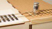
Richard a good tool for the final push in of the spikes is a square tip screwdriver with a small slot that also aids lining up the spikes also you can blacken the spikes before inserting them by simply heating them up and then letting them cool down. I have made a lot of spikes this way.View attachment 207678

View attachment 207679

Also check out all the various types of office type staples they come in a variety of sizes.
Michael

Michael thank you so much for all these notes.

I have just found out (from Four Types of Rail Spikes), a modern spike is 16 mm thick. This equates to 15 thou in 7mm scale, while my 26/6 staples measure 18 x 16 thou. So I will stay with these. I have a household stock of several thousand.

I have two BH turnouts for my first diorama, so if I use these then I need to build only plain track to begin with. This is for the traverser and its headshunt. I have limited space for a layout, so I want to make the fiddle yard look as nice as I can. Maybe, even good enough for model photography.
 
Reference Track including Project Datum

Richard Gawler

Western Thunderer
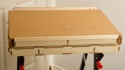
Ten days on, here is a fresh view of the baseboards to wrap this part of the project up for a while.
View attachment 188723
The board from my test track is now the foundation for the new boards. The Kallax underframe is on castors and the baseboard tops have ended up about 1.15 m above the floor. I find this comfortable for using three-links but too high for scenic work. The castors mean there is now room to store the fourth module under the Kallax underframe.

I have put the wagons here to get a feel for what this scheme can hold. There are four internal, two PO and two foreign. This is about the maximum without getting completely boxed in. The 200 mm headshunt module (in the distance) can hold Nellie and Blackwater (and my next two loco projects) but not Nellie with her tender truck nor (of course) the Y14.

I suspect the diorama would work better as a "small layout" if the loco spur came from the fiddle yard not the kick-back siding; but will be a better "test track" with the kick-back using the Setrack point. Maybe there is a compromise somewhere in here but my gut feeling is, this is my scenic test piece and test track; and The Layout is for later.

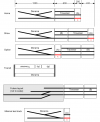
Last summer I gathered together four baseboard modules to form the basis of my first 7mm layout.

Basin with modules.png

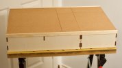
Track ‘x’ here will be the datum for the whole project. Primarily, this track defines the relationship between the “main line” of the railway and the pattern maker’s dowels in the ends of the modules. This track also sets up the locations of the tracks behind it, governed by the usual “six foot”. The traverser slides (of course!) so this track also sets the height of all of the other rail heads at all of the baseboard joints.

DSC_6035.jpeg
The locations of the baseboard sides are mechanically irrelevant in the scheme but it is nice to have them lined up.

DSC_6036.jpeg
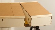
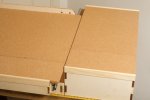
The joints aren’t too obvious until I open them up.

I have set the fronts of the pattern maker’s dowels slightly proud of the ends of the modules. Hopefully I can take rails precisely up the ends, and end up with tiny gaps at the joints.

DSC_6047.jpeg
The traverser is going to be a project in its own right if I decide it needs some kind of indexing or locking mechanism, because this will need to be within the module not on the top.

DSC_6044.jpeg
Above all, the cork gives me enough height to connect to my A6 turnout (build on thick card) without needing to dig downwards into the surface of the diorama module.

I also have enough height to lay proprietary track on future modules up to the three interchangeable modules. The idea is, nothing gets wasted as the layout evolves.

DSC_6042.jpeg
One conclusion from all this is, I think for any modular project it is imperative to build all of the modules yourself. I bought the traverser module secondhand and ready-built (and by mail order) and it has taken much work to bring it up to standard.
 
Last edited:

spikey faz

Western Thunderer
I have two BH turnouts for my first diorama, so if I use these then I need to build only plain track to begin with. This is for the traverser and its headshunt. I have limited space for a layout, so I want to make the fiddle yard look as nice as I can. Maybe, even good enough for model phphotography.
Hi Richard.
I have even less room than you for a 7mm/1ft layout. If and when I get around to building my layout (more likely a strip of track!) I'm seriously thinking of having the fiddle yard/exchange sidings fully sceniced. Otherwise I'll have a board full of bare track in full view, which seems a bit of a waste.

Mike
 

Richard Gawler

Western Thunderer
I can make room for a layout but I don't have room to build it!

The thought of so many track spikes is rather daunting, but I could do the traverser with Peco code 124 (their bullhead rail with a flat bottom) on copperclad sleepers as a temporary measure.
 

Yorkshire Dave

Western Thunderer
The traverser is going to be a project in its own right if I decide it needs some kind of indexing or locking mechanism, because this will need to be within the module not on the top.

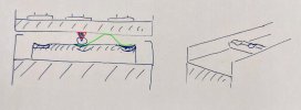
As the traverser bed is held in by the roller drawer slides at each end the indexing and locking mechanism can be as simple as a sprung wheel or roller held in a bracket or even a piece of sprung steel attached to the underside of the traverser bed with the wheel, roller or sprung steel traversing a piece of wood with dish indents.

With the spring not being too strong and the dishes shallow enough to just lock and hold whilst not requiring brute force to move it. A rather simple drawing to demonstrate the theories.

spring.jpg
 

Richard Gawler

Western Thunderer
Dave, this sounds ideal.

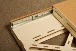
DSC_6053.jpeg
For those who haven't seen the insides of this traverser - there is plenty of space on the base for a strip with the indents, and space under the deck for the wheel on its spring.

It will do me good to make something functional and which doesn't need a "scale" appearance. Added to the list of things to do.
 

Richard Gawler

Western Thunderer
I have even less room than you for a 7mm/1ft layout. If and when I get around to building my layout (more likely a strip of track!) I'm seriously thinking of having the fiddle yard/exchange sidings fully sceniced. Otherwise I'll have a board full of bare track in full view, which seems a bit of a waste.

During a phone call years ago, Grainge and Hodder explained they could do their 600 mm traverser deck on a 1200 mm module. With the deck at one end, such a device could produce a one-piece diorama. I considered this, and with a 400 mm module next to the deck (i.e. the deck in the middle of the assembly) but decided I wanted a scenic diorama without the moving ground effect.
 

Yorkshire Dave

Western Thunderer
I've been looking at the Grainge and Hodder suite and it's a shame they do not produce a 800 or 900mm traverser suitable to hold a HO Br141 or Br111 and 2 Silberlinge. 600mm is no good when Silberlinge are 303mm long!
 

Richard Gawler

Western Thunderer
I now have an inconsequential-looking length of track to align the tracks on every other module.
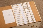
DSC_6065.jpeg
In summary:
  • A fresh piece of Chartwell’s finest (imperial graduations)
  • Two lengths of double-sided adhesive tape
  • PVA glue dabbed under the sleepers in between the lengths of tape
  • Code 100 Hi-Ni rail from Kalgarin Models
  • Plywood sleepers from C&L Finescale
  • Spikes from Rexel no.56 staples, blackened and separated using heat
The rail is soldered onto brass screws near each end. The staples are pulled tight over a scrap of 0.8 mm wire and trimmed flush to make the spike heads.

I am pre-drilling holes for the spikes. This lets me hold a spike with pliers, insert the head past the rail head (this is rather broader than on the usual 00/H0 code 100) and rotate the spike to rest its head very near or just touching the web of the rail. The holes are large enough to take a dab of CA glue placed on the bottom of the spike and taken with it into the hole. This all seems to have set solid overnight.
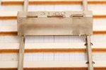
DSC_6056.jpeg
The rail has a slight lateral curve in its natural state, so arranging it to curve inwards lets the second rail rest naturally against the track gauge.

I have closed up the gap mentioned in earlier posts. It remains for the camera, and if I hold the model up to the light. If the overall effect is what really counts, then this is down in the noise floor.
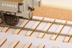

DSC_6069.jpeg
I remembered to put the dropper wires on before laying the rails :)

The pairs of spikes photographed at the Mendlesham seem to be rather sparse so I have missed these out for this short length. I will try to remember them when I try to represent the rail joints on the diorama.

These tiny spikes are going to transmit all of the running noise into the baseboard structure. The cork is now only here to provide a flat surface and a better appearance on the areas without scenics.

Regarding expansion, I have built this at an ambient temperature of about 17 degrees C. This is roughly half-way between the extremes of a car boot in winter and the house in a hot summer. Fairly obviously, the only way the rails can move is upwards but I am optimistic these are short enough to stay put.

I can try modifying a small screwdriver to hold the spikes but at the moment I have coped using the small pliers. I have managed about two minutes per spike, so perhaps 90 minutes to build this after preparing all of the parts. So I can expect about three hours per yard, just about fast enough to stay below my boredom threshold.
 
Last edited:

Yorkshire Dave

Western Thunderer
I remembered to put the dropper wires on before laying the rails :)

Aaaahhhh.... cheeky mode on ;) - could the dropper wires have been soldered to the rail where it was going to sit on top of a sleeper and a groove taken out of the sleeper so it sat down? That way you would maintain the light railway effect with 'daylight' between the rail and ballast as seen in the Mendlesham photo, and wouldn't have to ballast to the top of the sleeper to hide the wires. :)

Cheeky mode off...:D

And thinking a bit further to hide the brass screws. Could they have been countersunk into the sleeper and the rail soldered to them afterwards and dummy spikes added? The screws would then not appear under the rails should you not want to ballast to sleeper top level?

Apologies for bolting horses and stable doors closing :oops:.
 

Osgood

Western Thunderer
Drill right through a spike pilot hole.
Feed wire (pretending to be spike) up protruding from sleeper where spike should be.
Bend over and solder to foot of rail
:rolleyes: :D

Rip it up and start again.

 
Last edited:

Richard Gawler

Western Thunderer
The last couple of posts are surely showing how a good forum works - and WT is a particularly good forum.

Thinking about only the dropper wires to begin with, it never occurred to me to try to completely hide them physically. The plan was to ballast half-way up and disguise the rest with paint. At the time of the build, I was more concerned about giving myself a little lateral slack so the rails ended up dead in line at the ends of the board.

Of course, the technique I have got away with in smaller scales becomes a bit too visible in 7mm scale. The sensible approach is to try out the new methods for droppers from @Yorkshire Dave and @Osgood on the next length of track. If I can make Tony's method of using a disguised spike work for me, I can go back to the first length, add new feed wires and remove the existing ones.

I have no intention of ripping anything up. There may be an issue with rail alignment at one end of this module, but I'll wait a wee while for any follow-up on the feeds before posting. "Likes" are good (they suggest at least some people are broadly nodding in agreement, or of course cheerfully enjoying a beer) but constructive comments can add more value.
 

Osgood

Western Thunderer
Follow-up on feeds - don't you mean feedback?

Well despite having acquired some NS Code 100 FB rail from Skippy a while back I have yet to use it - droppers hadn't even appeared on the radar.
It was only reading your trials that suddenly made me realise there was surely a simpler way - and as a bonus the soldering is in a flat plane! :thumbs:
I can't see it wouldn't work out well.
 
Last edited:

Richard Gawler

Western Thunderer
Follow-up on feeds - don't you mean feedback?
Consider:
A post on a track feed
Feedback on the post is a finite thing which represents feedback but is not explictly identified as such
Then follow-up on the feedback

A post on a feedback controller
Feedback on the post may well mention feedback, but always represents feedback in its own right
Then follow-up on the feedback

The track feed is unaware of the type of control employed; so probably, no :confused:
 
Last edited:

Richard Gawler

Western Thunderer
And thinking a bit further to hide the brass screws. Could they have been countersunk into the sleeper and the rail soldered to them afterwards and dummy spikes added? The screws would then not appear under the rails should you not want to ballast to sleeper top level?

Yes and no.

I have probably mislead people including myself by describing track x as a datum. Really, only one end of this track is the datum.

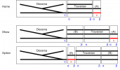
Each module of the fiddle yard has two mating ends, while the diorama has only one. The layout has two viewing sides, so the terms left and right are potentially ambiguous; so I will call these ends α and β for the fiddle yard, and γ for the diorama. Sorry the default font on WT gives a slightly crummy-looking gamma but I've done the drawing . . .


Identifiers for build sequence.png
I need to be careful to make sure I end up with a modular layout not a sectional one. "Home" and "Show" are relatively easy to make because module (A) is a terminus; "Option" is much more difficult.

So the correct sequence to lay the tracks onto the baseboards should be this:
  1. (A)-α based on nothing (the singular datum)
  2. γ based on (A)-α (this creates a second-generation point of reference to build other α ends)
  3. (Traverser)-α based on γ (this creates a third-generation point of reference to build the β ends of (A) and (B) but not the traverser)
  4. (A)-β based on (Traverser)-α

and so on.

Much the same as setting up the pattern-makers dowels last summer.

I may need the visible screw heads at (A)-β so I can tease the rails sideways. Because I really should have spiked down only the first half of track x at this stage.

I have started to grind down the edges of the screw heads and I can finish this off after I know the rails are in their final locations.

What of the all the remaining screws? If I countersink them into the tops of the sleepers I will surely leave burn marks. This is a problem if I stain the sleepers; not a problem if I paint them. I will have to paint the sleepers on the diorama because the two points have plastic sleepers. So I guess, I will end up painting the track on the fiddle yard to match. Clearly I need to have a go at the track on the diorama, see how I get on, and define γ.
 
Last edited:
Top