SimonD’s workbench

simond

Western Thunderer
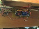
Didn’t like the big green multi plug (well, I do, but not for this) so replaced it with a row on 0.1” pins, and fitted the three boards onto a scrap bit of GF circuit board. Managed to reconnect the ribbon cable from the central panel, and then relocated the wiring from the old relay to the new ones. All installed and working. :)

image.jpg
The wiring really isn’t as tidy as it should be….
The black & white twisted pair are the link to the tortoise point motor to ensure that programming can only be turned on when the points are correctly set to prevent mishaps.
The black and white pair on the right are the programming track feeds from the Lenz Zentrale, green & blue are track feeds from the booster, and the twisted red & black are the outputs to the programming track.
Red & Brown are +12V & ground supply to the Arduino and other boards, dropped to 5V by a 7805 which you can see lower left on the board the Arduino’s on.
Yellow and Orange are Can H & Can L respectively.
And the termination resistor jumper is on the points receiver at the moment :)

And no more excuses, turntable over the weekend…
 

simond

Western Thunderer
Mission accomplished.

And a right pita it was too, made far more complicated by my ineptitude coupled with a somewhat daft ability to save two files with the same name because of the way the Arduino IDE saves sketches. So I corrupted the wrong file :(. And so I had to rewrite it… And then wasted an hour because I’d changed a connection, but failed to update the rewritten software to account for it.
the other daft thing is a data sheet that says “you can…” and when you do, and it doesn’t work, and you read on several pages, there’s a bit that says “except”, which wasted another hour.

anyway, it’s all a learning experience,and it seems to work as intended. I have not yet managed to get the lighting installed but the dummy system worked ok, so I’m optimistic. Hopefully not unreasonably so!

so, having left it off for half an hour, I just turned it on and the turntable is initialising itself correctly, the point motors all switched and returned, and…. it‘s not working properly. There’s a bug somewhere which means I have to prod the reset on the control panel, and then it all works fine. Shouldn’t have to do that :(

G’night all
 

simond

Western Thunderer
Whilst waiting for the morning coffee, I turned it on, and it initialised correctly and worked as intended.

this suggests to me that something is marginal either timing wise, or voltage supply, or possibly a combination of both.

a question to address this evening, maybe.
 

michael080

Western Thunderer
That's why I don't like the arduino framework. There are far too many inconspicious depencies between the functions. Many of them rely on timers and there is no warning if both functions try to use the same hardware function.

Fist thing I do with arduinos is to remove the aduino farmework. Atmel studio is your friend. Program it in bare metal C and you are on the safe side.

Sorry for the rant,

Michael
 

simond

Western Thunderer
Michael,

don’t apologise, no need.

My programming history goes back to the late 70’s, using Algol & Fortran on punch cards (how do I wish I’d kept a binbag of chads, perfect bricks…) a Sinclair Spectrum in the early 80s, and then HP Basic in various flavours both whilst studying and subsequently at work, and some other stuff I can’t recall. Then, many years of not programming, and then the easy approach offered by Arduino and I’m having a great time…. Mostly :)

I thought I’d sussed it out this evening, as the voltage into the Mega was only about 4.7, so I fitted a better supply, but it’s still not firing up first time every time, but I’m now pretty confident that it’s not an inrush/brown start problem. As you say, it’s almost certainly a timing issue, I’ll play with it, but I want to get the layout lighting working next.

need to find some FETS…

atb
Simon
 

simond

Western Thunderer
A little software fettling last night seems to have fixed the ”start then reset” issue, I increased a delay between the “setup” and “loop” to a second, and the issue seems to have disappeared. I say “seems to” because of course I can’t say it won’t recur next time I turn the layout on. I guess the more times it initialises correctly, the less probable the glitch becomes, but testing for a non-event is a fool’s errand!

I’ll get the FETs ordered today and maybe get the layout lights working next week.

atb
Simon
 

simond

Western Thunderer
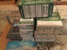
New toys…

image.jpg

Veroboard, resistors, microswitches, leds, FETS and NAND gate chips.

Two projects: the multi-channel variable output lighting for PD loco, and the resignalling for John’s North Whitton station.

The latter will comprise an Arduino handling locking & driving servo point motors with live frog switching, and 2-aspect colour light signalling from a frame of miniature panel switches. I’m aiming to 3D print signal heads to suit standard 5mm leds, and servo holders which will support & protect the servos & microswitch from the elements, and convert a full 180 degree rotation to the 4mm or so travel required to operate a Peco 0 gauge point.

(the chips give the opposite output to their input, so the Arduino simply drives the red led - the green will be off if the red is on, and vice versa, saves lots of work)

I’m going to get the lighting done first!
 

michael080

Western Thunderer
the chips give the opposite output to their input, so the Arduino simply drives the red led - the green will be off if the red is on, and vice versa, saves lots of work
it's the old story: software engineer says "change your hardware". Hardware engineer replies "change your software". Quite easy to see to which side you belong.
 

simond

Western Thunderer
Other news,

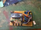
image.jpg

CAN-connected Arduino with 4-channel FET lighting control. Two pins for a jumper and 3 FETS to fit, and a bit of checking, before installation, hopefully working tomorrow evening.

Unfortunately a visit from Cap’n Cockup rather spoiled things, but I hope I have recovered the situation. I’d mislabelled the FET pins when developing the schematic, so I had to take some bits off, and remake some connections - the soldering on the other side is not pretty…
 

eldavo

Member
Depending on how stable and clean your power supply is you might consider adding a couple of electrolytic capacitors from 0v to the input voltage and also 0v to the output voltage of your regulator. In my experience the nano is very susceptible to brown outs and will reset itself at the slightest provocation!

Cheers
Dave
 

simond

Western Thunderer
Thanks Dave,

so far so good!

there is a cap on the +12V busbar where it comes in from the PSU - the 4 header pins you can see top left are +12, GND (both to the main busbar), CANL & CANH. The Arduino is powered via the 7805 off the 12V and common GND - I could drop a cap on the +5V rail easily enough, it could sit top centre, but I do have to put a couple of fixing holes in at some point, so it's not dangling on its wires!

I did end up fitting a load of caps on the turntable controller, which has a stepper output, but from memory, the points controller (tortoises) was fine.

I'll see where we get to this evening, keep your fingers crossed that Cap'n C stays away.

ta
Simon
 

simond

Western Thunderer
Much faffing with PCBs and software, it’s working, after a fashion.

Whilst I can turn the lights on from the control panel, and I can adjust them, it is not working in the intended way, particularly as turning the lights off doesn’t work properly at all! Anyway, the hardware seems to work, and it’s installed.

I shall have to review the control panel program.

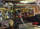
image.jpg

That’s the beauty of DCC, only two wires. :D:)):)):))

and the kit stash has been augmented by a selection of Adrian Swain’s kits from Dave Parkins’ “old stock sale”.

wheels and decent buffers to purchase, and this will provide enough entertainment for several winter’s evenings!

image.jpg
 

simond

Western Thunderer
Thanks John,

Well, all the points are really operated by strings and the locos are clockwork, the flashing lights are only there to impress :)

When it’s all working and tested I’ll write up a little billy-doo and post it in the hope that it’ll be useful to someone
 
Top