SimonD’s workbench

simond

Western Thunderer
Fairline 36, certainly too big for two of us now the kids have flown the nest, but we’d never get our money back if we sold her and we love our hols in France

Think of it as a depreciating (mobile) holiday home…


And the annoying expensive days are more than compensated by the dolphins frolicking around the boat as you meander to the next port.

And it’s a lot cheaper to run at 8kts than 18!
 

simond

Western Thunderer
Workbench….

well, it needs clearing, its a shambles, and I’ve done very little at it for weeks, mainly, happily, because we’ve been gallivanting around Europe on boats and motorbikes, and good stuff like that, and of course, there was a certain amount of boat and motorbike fettling being done (though mostly at the other workbench) too.

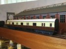
I haven’t cleared it (yet), but I have made a couple of CV adjustments on John‘s coal tank, glue securing crew still setting, and fitted the glazing and glazing bars to my newspaper van.

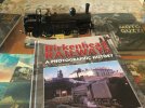
I also received the Photographic History of Birkenhead Railways, by MHRG released recently by Lightmoor Press. I’ve only read the first chapter or so, but it contains some wonderful photos, and some of my childhood memories. I can imagine a few WT‘ers will enjoy…

image.jpgimage.jpg
photos being cruel, show a certain tidying up of paint may still be required…
 

simond

Western Thunderer
Thanks Phil,

On my recent trip to the SVR, in addition to not finding the vehicle with Dean brakes, I also failed to get into the goods shed at Bewdley!

such is life.

That crane is curious, I expected one that was a wooden "gallows" pivoted at floor and a roof beam, possibly with a counterweight, probably with a big pulley. I'd expect that one to be outdoors where there isn't a roof beam to provide stability on high!

cheers
Simon
 

Richard Gawler

Western Thunderer
At least you made it to Bewdley. We bought rover tickets for the whole line but spent so long at the 0 gauge show at Highley we ran out of time to go any further, and had to return to Bridgenorth :rolleyes:
 

Phil O

Western Thunderer
Thanks Phil,

On my recent trip to the SVR, in addition to not finding the vehicle with Dean brakes, I also failed to get into the goods shed at Bewdley!

such is life.

That crane is curious, I expected one that was a wooden "gallows" pivoted at floor and a roof beam, possibly with a counterweight, probably with a big pulley. I'd expect that one to be outdoors where there isn't a roof beam to provide stability on high!

cheers
Simon

Simon,

So did I, but it does seem to give another option.
 
Arduinos and CAN

simond

Western Thunderer
Arduinos. And CAN.

when I built PD loco, I had in mind the intent to incorporate it into a larger layout at some indeterminate point in the future, when we get our extension built, so the control panel is on the end of a wander lead. I wanted to include points, turntable and lighting control, along with a socket for the Lenz x-bus, and I also wanted to use a standard 25-way d-plug cable, as nobody wants to make up leads, and they can get damaged with use, so easy replacement is also desirable.

There aren’t enough wires in a 25-way cable! I was advised that using I2C comms between Arduinos was likely to lead to problems, but it worked when I first installed it, and it still works now, but not reliably, and that’s a PITA, so over the last few weeks, I started to rebuild things, to use CAN comms. The MCP2515 modules are cheap and after a few issues, I have them communicating happily, so now I’m reprogramming.

Inevitably, the Arduino pins that are required to communicate with the CAN modules were already used, so that required some rewiring too. This would not have been the case had I started with CAN of course.

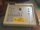
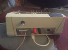
The control box is functional, though not pretty, it’ll be much improved by a laminate front panel with trackplan, and a more attractive set of buttons for the turntable. The other switches are lights and program track.image.jpgimage.jpg

the red button is a reset for the Arduino mega within, the red & black 4mm sockets are track DCC to facilitate use of the test track & rolling road, and the DIN socket allows a Lenz/Roco controller to plug in. The knob is the brightness control for the layout lighting, of which there are 5 channels. The orange and white wires are the temporary CAN connection.
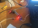
image.jpg

This is a typical slave - the CAN interface is the nearer board, and it’s connected to the Arduino Nano which will eventually be reconnected to the turntable stepper motor. Similar arrangements are connected to the points controller and lighting dimmers.

the CAN interfaces were about 3 quid each, the Arduinos similar money, so it’s within the bounds of realistic money to put a CAN interface and an Arduino pretty much anywhere on a layout (eg in a building, just to have individual lighting control, though you could program a few other features/gimmicks/whatever as well)

it’s all spread across the bench, a table and my workbench chair at the moment, but a good push this evening will sort out the controller programming, hopefully before Hislop & Merton enjoy the weeks’ events.

The lighting slave controller is done and works. It also operates a relay which connects the front siding to the programming outputs of the DCC but which is interlocked with the crossover, hopefully this will continue to prevent me reprogramming my entire loco fleet to the same address…. I can install that over the weekend and hopefully get the layout lighting connected & working nicely.

The points slave controller has been built on a piggy-back board, so, if I’ve got it right (fingers firmly crossed) I can unplug the Nano that is on the points control board, and simply plug the piggy-back board in. I hope.
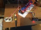
image.jpg
points piggyback board lower left. The white panel carries the lighting PWM outputs and the programming track relays.
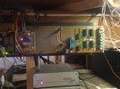
image.jpg

This is where it has to go. The Arduino Nano on the left is the turntable controller, that on the right is the points controller, the ICs are NOT gates to provide the reversing polarity for the Tortoises, the LEDs to the right are green/red and change colour to indicate what the tortoise should have done. Was quite pleased with that, it all works rather well.

The turntable board will require a little reallocation of pins to accommodate the CAN interface. That or another piggy-back might be easier. Might get that done over the weekend.


More soon
Simon
 

Focalplane

Western Thunderer
Well, Simon, you know I have a hard time understanding all this but you are “the man” so I shall follow with interest. The other evening I watched a youtube video about a computerized operating system for a huge model of Southern Pacific’s Donner Pass. Here is the link:


Also way over my head, what really caught my attention is having two cab forwards working a train , head end plus rear helper. Their controllers allowed the exact speed to be matched so no buckling of the train while climbing the pass.
 
Last edited:

simond

Western Thunderer
Thanks Paul, the video/model is impressive.

If I’m ”the man”, then I’m worried, things did not go to plan, and whilst I have caught up a bit, I do not know what did not work properly. I think I’m back to where I was around supper time yesterday…. I assume I changed something without realising/meaning to, and this has somehow compromised the comms. And if you can’t find a fault, but it goes away, you can bet it’ll return…
 

michael080

Western Thunderer
There aren’t enough wires in a 25-way cable! I was advised that using I2C comms between Arduinos was likely to lead to problems, but it worked when I first installed it, and it still works now, but not reliably, and that’s a PITA, so over the last few weeks, I started to rebuild things, to use CAN comms. The MCP2515 modules are cheap and after a few issues, I have them communicating happily, so now I’m reprogramming.
Wow, I like to see some electronics work here! Sorry to hear about your problems with I2C, I avoid it at all cost after I had to dump my push button type signal box. It worked all nicely until it reached full scale with 42 elements and then ... :(

IMG_2519cr.JPG

I should have reprogrammed it, but the layout is history and so is the signal box.

good luck with your project anyway! I am sure you are on the right path with CAN.

Michael
 

simond

Western Thunderer
Thanks Michael, the I2C is a lesson learnt, but the CAN has given me a surprising headache, with this intermittent glitch.

Let’s see what tomorrow brings, I do have to go out briefly, but the weather forecast is perfect for modelling…
 

adrian

Flying Squad
Thanks Michael, the I2C is a lesson learnt, but the CAN has given me a surprising headache, with this intermittent glitch.

Let’s see what tomorrow brings, I do have to go out briefly, but the weather forecast is perfect for modelling…
My apologies if you've already got it covered, not an electronics expert myself but I do remember the instructions for the Merg Canbus system stipulates twisted wires and a termination resistor to avoid "glitches".
Screenshot 2022-10-23 at 23.30.47.png
 

simond

Western Thunderer
Thanks Adrian, I’m a “rude mechanical” as Shakespeare would have it, but have a little experience with CAN from work, and the boat, which uses NMEA2000 networking for the Nav instruments, which is CAN with marine connectors, and price tag, of course.

Termination resistors are debatably not necessary on smaller, and slower networks, but will improve bus performance, and the MCP2515 boards come with a pair of pins for a jumper which make it ultra easy to connect them, so I have used them. The protocol is to only put resistors on the outer ends of the spine of the network, and not on any branches or “droppers”. And no loops are allowed.

Twisting wire pairs is good advice as it helps reject interference. I’ve no idea if the pairs within the 25-way I’ve used are twisted, but it seems to work, I’ll see if it gives trouble when I reconnect the Lenz controller, as the X-bus, DCC track connections and CAN are all in the same 25-way cable.

I rather hope the issue that I experienced on Friday evening was a bad connection, I did remake a couple of connectors within the control panel, and it has not recurred, and I have no idea what else it could be, so fingers crossed.

I managed to get the points control working yesterday, the “piggy back” board I made dropped in and once reset, just worked. It’s great when a plan comes together! Turntable next…
 

Dog Star

Western Thunderer
This article will shortly be made available in English but Google Translate keeps going for a lie down.
;)
I just ask the Kids... I get three answers and each is different!.

Simon-with-a-D, how do you choose the "outer ends" where there is star network to provide DCC to all tracks?

regards, Graham
 

Richard Gawler

Western Thunderer
There will be people here who think a terminator is big Arnie with a hyper alloy combat chassis inside and a peer is someone in the House of Lords or a place with a candy floss machine (note careful wording after possible political content) but a couple of terminators won't do any harm on a simple peer to peer link between only two nodes. I suggest, pop them in.
 

simond

Western Thunderer
There will eventually be four nodes, the panel has its terminator already, the points slave has one too, but it might be moved in due course, deciding where the far end is, is questionable because the network is something like this (panel)-------V-V-V-V, where the "V"s represent the droppers to the program track relay, turntable, lighting dimmers and points respectively. The issue is that the program track relay will be further from the panel than the points. I guess it is so easy to fit or remove the jumpers, I'll play it by ear.

Graham
Track-supply DCC doesn't require terminators though I believe they are recommended for the Lenz x-bus (command bus)

Simon
si tu le preferes, je pourrais le taper en francais...
 

simond

Western Thunderer
Not turntable next because I didn’t feel like it…. It’ll require some rewiring of the stepper controller, so I opted to leave it, and do the program track relay instead. It needs something to mount the boards on, but it works :)

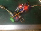
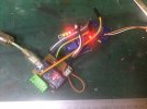
image.jpgimage.jpg
spot the difference... The green lights in the second image indicate that the relays are “on”. The two wires coming in from the right are the temporary CAN connections, and the USB is the temporary power supply.

The green connector lower left will supply 12V and the CAN when it’s installed. The orange loop is a temporary jumper, this will be looped through the Tortoise switch to detect that the crossover that connects the program track to the rest of the layout is set to prevent inadvertent mis-programming
 
Top