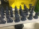
SimonD’s workbench

simond

Western Thunderer
Highly unlikely, but hypothetically possible, they started production in 1930 and I’m sure I can whistle up an appropriate local registration plate. In any case, it’ll need to be at the back of the layout as it’s a bit small…

and the wrong model. Wikipedia has some photos. As a military model, it’s unsurprisingly a WW2 era version.


never mind.
 
Last edited:

Yorkshire Dave

Western Thunderer
Opel Blitz and Bedford (W and M series) trucks are a rabbit hole......:).

Although Bedford and Opel were owned by General Motors - the trucks were similar but the difference was in the detail and year of production - namely the cab, radiator and bonnet (louvres).

I looked at converting one of the 1/48 models into a UK Bedford M series introduced in 1939 with the cab as portrayed by the model but there was a lot of work required around the radiator (to convert to bull nose) and bonnet louvres.

The earlier Bedford built W series trucks had a different cab, bonnet and radiator with the radiator initially the same as the Opel Blitz.
 

simond

Western Thunderer
To quote Mrs Ramsbottom, “eee, I am vexed”.

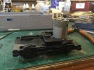
a wee while back I acquired a Big Big Hymek with the intent of making up an R/C loco, nothing very serious, a bit of fun. I did a bit, then chucked it in the cupboard awaiting the Ultrascale gears. Meanwhile I sketched up some bogie schemes to 3DP, and everything came together at Kempton, where I picked up a couple of delrin chain & sprocket kits.

I’ve had two print failures, due to poor support, but today‘s attempt printed.

image.jpg

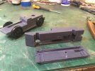
I can’t say they “printed fine” but the print assembles to the bogie as you can see.

image.jpg

what is not evident in these pictures is the distortion in the print. One side is significantly deformed and I suspect the axles are not parallel in plan (there’s a tiny bit of rock, but that aspect is quite good)

image.jpg

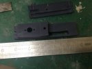
The keeper plates fit after a bit of fettling, which was to be expected, I guess, but the distortion in the main part of the bogie is not great.

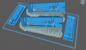
I guess this is down to the way I supported it, which, if anything, seemed OTT to me, but clearly wasn’t.

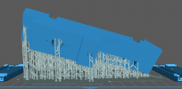
A couple of screenshots of the supports from the laptop;-

1688226106233.png

1688226142386.png

any suggestions or advice from the congregation would be most welcome!
 
Last edited:

Giles

Western Thunderer
Hi Simon
They look like "fine" supports to me, I should use the standard size given the mass (although if you've had non break away that may not be too much of an issue....) , and I would certainly be tempted to steepen the overall angle, which by eye looks to be around 20 degrees? I try to print at 37 degrees when I can.
Good luck!
 

simond

Western Thunderer
Giles, thanks.

the supports are “heavy”. No failures this time.

I originally set the bogie body at 45 degrees both fore-aft and left-right, then made it more shallow :( it was actually about 15 degrees.fore-aft.
Two approaches suggest themselves: to go for a very steep angle fore-aft, such as 75 degrees, and whatever looks feasible side to side, or to plant one side on the build plate, though this carries the risk of not draining nicely, which would tend to affect the slot for the chain.

I might print one of each and see what happens.

thanks again
Simon
 

Giles

Western Thunderer
Another thought (do forgive me Simon, you've probably thought all these things through anyway....) might be to hollow the print out a bit, adding a bit of bracing as necessary, so as to reduce the wet load of the print.
 

simond

Western Thunderer
Thanks Giles, I did ponder that, from a weight, and from an “even up the stresses” point of view. Having pondered, I then didn’t do it. :). version 5 if required…

I have the main body angled at 15 degrees from vertical, hopefully in such a manner that the resin will be able to drip away unhindered in the critical areas around the axles. I modified the step on top to provide a run off there too.

Predicted time is 7 hours and some minutes, it’ll finish after midnight, so can it drip until I get up tomorrow morning. I can wash it whilst the coffee‘s making, dry whilst I’m eating brekky, and leave it in the uv when I toddle off to the office.

It'll be ready to use, or to go in the bin, when I get home!
 

simond

Western Thunderer
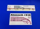
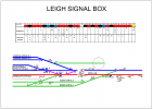
Whilst discussing Signal Box Diagrams on @David Waite 's Chimtonstoke thread, I didn't imagine I'd be asked to do one last Sunday.


1688645028714.png

This is of course in the "entirely adequate" camp, rather than a work of art, but, it took only 2 hours.

Drawn on TurboCAD to A3 size. Laminated, so hopefully will not go mouldy in a garden shed!

atb
Simon
 

simond

Western Thunderer
I’m glad I drew it on the ‘puter.

I spotted a trackwork error this evening, but the layout owner (who knows a bit about signalling) didn’t spot it :)

Anyone up for the challenge?

It’ll only take 5 minutes to fix, and the same again to print and laminate!
 

John Duffy

Western Thunderer
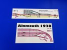
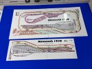
I recently made these for a friend. Sublimation printed onto aluminium so that switches and LED can be mounted directly onto the panels.

IMG_8850 2.jpegIMG_8851 2.jpeg

Happy to make some for you at the special WT rates if you need them more substantial.

John
 

Attachments

  • IMG_8851 2.jpeg
    IMG_8851 2.jpeg
    165.4 KB · Views: 5

David Waite

Western Thunderer
I’m glad I drew it on the ‘puter.

I spotted a trackwork error this evening, but the layout owner (who knows a bit about signalling) didn’t spot it :)

Anyone up for the challenge?
Hi Simon
Only Two Hours “Ahhhhh not fair” just goes to show what technology can do, lovely job by the way.
Thanks for the plan I enjoyed reading through the interlocking chart, the 3 way point on the down is interesting .
Re the challenge
Catch points on the goods line would be nice.
l cannot figure out what signal 30 is, is it a colour light signal?

David
 

Bill Campbell

Western Thunderer
The shunt move from the arrivals platform to the up line via crossover 6 does not appear to be signalled - this would be necessary for disposal of empty carriage stock.

Regards.
 

simond

Western Thunderer
thanks guys.
the “Captain Mainwaring deliberate error” was the upper point of crossover 17. Its normal position is shown incorrectly. Getting a rake of carriages in or out would have been a challenge…

there was also a missing 16, a backing signal into the carriage sidings from the up line, and 31 is a spare, so I’ve added that too. And coloured in the platforms in pale grey.

Bill,

you’re right, but there are no dummies on the layout. There are a few moves where a shunt arm would be appropriate.

David

you’re so right, a catch would make sense. Signal 30 is a colour light distant.

The layout has survived some thirty summers, and is showing some age-related issues, not least that the original signal box diagram has faded and legibility is an issue. John built it pretty much single handed when he was in his fifties & sixties, and he's not quite as agile as he was, but the trains still run on Thursdays!
 

David Waite

Western Thunderer
Hi Simon
Unless I’ve missed seeing something in the locking chart please correct me if I’m wrong,
17 needs to lock 6 normal and 6 needs to lock 17 normal , re two conflicting movements one from the carriage siding to the up via points 17 while points 6 could be reversed allowing a movement through the crossover or visa versa.
David.
 

simond

Western Thunderer
David, thanks.

I didn’t design it…

you’re right that 6N should be required before pulling 17 & 18, and though the diagram above doesn’t show it, 6N would also be required before pulling 16 (“invisible” backing signal for entry to carriage sidings & loco) and, in an ideal world, a generous portion of dummies.

I have no doubt that David @Genghis might also be able to add sage advice…. But the only changes that will happen are point motors where the rodding has given up the unequal struggle with time, weather and gravity, and some LMS pattern two aspect heads where the semaphores have similarly given up the ghost.

I will post the corrected diagram!

thx
Simon
 
Bolster wagons

simond

Western Thunderer
Meanwhile…

image.jpg

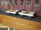
John Duffy kindly sent me a couple of laser-cut sets of bits for a pair of North British bolster wagons, so I’ve been doing them. Ambis axleguards, 3DP buffer stocks, home made bolsters. Lots still to do, but on their wheels, at least. After a brief flurry of activity, they’ll probably stay like this for months…

atb
Simon

reference Help required producing unusual buffers.
 
Last edited:

simond

Western Thunderer
A slight diversion - I do intend to 3DP the springs and axleboxes for the bolsters, and some other details, but given my predilection for diversions, I joined Alan Buttler’s Modelu Patreon, as an Early Bird member.

The Patreon concept is that you pay a monthly fee, and receive data downloads of five of Alan’s scanned characters, there’s also a Welcome Pack of five characters to choose from, which you also download. You then print as many or as few of each as you wish. I guess if you intend to populate a layout, it’s probably going to work out rather cheaper than buying figures individually, but of course, you’ll not want five identical Nora Batteys…

Additionally, you get to vote on the next month’s pack, and there’s a discussion forum for the members of the “club”. There are also discounts for other purchases.

I will print my first figures tomorrow, and report further.
 

simond

Western Thunderer
Pleased to report that the Figures all printed well, using FNG at my usual settings. All the supports worked. A couple of places where the print was so thin it left a hole in the brim of a hat, and the corner of the foreman’s clipboard. Not stressed about that! The figures are definitely up to Modelu’s normal standard.

it’s definitely better to set the printer off in the morning and clean up after work, than set it off at night, and then rush around trying to clean up and get the prints into the curing box whilst trying to eat brekky and feed the cat (who will not be denied, or delayed!) in time to go to work.

I shall paint a few figures when I’m in the mood. Assuming that each month there is at least a couple of figures which are usable for my era, it’s a good deal for me, and it seems like a very good approach for Alan & the Modelu team.

I hope it works out.
 

J_F_S

Western Thunderer
Whilst discussing Signal Box Diagrams on @David Waite 's Chimtonstoke thread, I didn't imagine I'd be asked to do one last Sunday.


Many thanks for posting this Simon and sorry to drag your exellent thread back to it. There are a few real 'howlers' in the locking - some of which have been pointed out - (eg 19 is seemingly free to pull at any time) and here is not the place for an extended debate, but there is one important locking principle which is worth mentioning that is entriely missing from the locking chart and I wonder if you would be willing to repost the revised diagram in the PW and Signalling sub-forum as a catalyst for discussion?

Just in passing, here are a couple of box diagrams I did in MS Powerpoint: I could hate PPT for a million reasons, but it happens to be quite good at this stuff!

Diag.jpg

Exeter West - an exact copy of the box original.


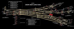
Crow Nest Diagram black.jpg

... and Crow Nest Junction - my attempt to recreate the original LMS "White on Black" style. Both of these are very interesting boxes to work!

I have threatened to do a brief "tutorial" on how to do these in Powerpoint as many people will have access to it and once you know how, a simple diagram is VERY quick to do - much less than a couple of hours!!!

Hope that is of interest.
 
Top