simond
Western Thunderer
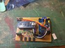
Didn’t like the big green multi plug (well, I do, but not for this) so replaced it with a row on 0.1” pins, and fitted the three boards onto a scrap bit of GF circuit board. Managed to reconnect the ribbon cable from the central panel, and then relocated the wiring from the old relay to the new ones. All installed and working. 
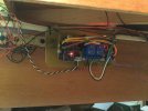
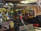
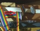
The wiring really isn’t as tidy as it should be….
The black & white twisted pair are the link to the tortoise point motor to ensure that programming can only be turned on when the points are correctly set to prevent mishaps.
The black and white pair on the right are the programming track feeds from the Lenz Zentrale, green & blue are track feeds from the booster, and the twisted red & black are the outputs to the programming track.
Red & Brown are +12V & ground supply to the Arduino and other boards, dropped to 5V by a 7805 which you can see lower left on the board the Arduino’s on.
Yellow and Orange are Can H & Can L respectively.
And the termination resistor jumper is on the points receiver at the moment
And no more excuses, turntable over the weekend…


The wiring really isn’t as tidy as it should be….
The black & white twisted pair are the link to the tortoise point motor to ensure that programming can only be turned on when the points are correctly set to prevent mishaps.
The black and white pair on the right are the programming track feeds from the Lenz Zentrale, green & blue are track feeds from the booster, and the twisted red & black are the outputs to the programming track.
Red & Brown are +12V & ground supply to the Arduino and other boards, dropped to 5V by a 7805 which you can see lower left on the board the Arduino’s on.
Yellow and Orange are Can H & Can L respectively.
And the termination resistor jumper is on the points receiver at the moment

And no more excuses, turntable over the weekend…

 . And so I had to rewrite it… And then wasted an hour because I’d changed a connection, but failed to update the rewritten software to account for it.