SimonD’s workbench

simond

Western Thunderer
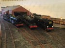
thank you all for your generous "likes". The b****y turntable has suddenly decided not to find its zero point, which is a bit tedious. MrsD complained about the layout "whining" the other day, and I realised that rather than turning to find the datum point, and then setting itself to the coal road, it had been rotating aimlessly for about an hour... I'll have to sort that one out.

Anyway, some folks will be aware that I have recently become the proud owner of an Elegoo Saturn 2, 8K 3D printer (it's like another language, it's all abbreviations and acronyms!) and that I installed it in MissD's bedroom on Friday. No further progress :(

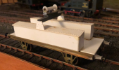
A number of reasons, but the key amongst them is that I have not developed the model I wish to print to my satisfaction. My "first attempt" was to be the two tool boxes, and the jib support for an L15 match truck, the chassis of which I constructed as part of the breakdown train some two years back. I had built a plasticard rendition of the boxes, but they lack detail as I was putting it off, waiting for this moment.

BUT

The drawings I have (ABT page 221) are inadequate, I have some pictures taken at Didcot of a similar wagon some time back, but i'm chasing my tail trying to make a decent detailed 3D rendition of a thing for which I simply don't have enough data. So when I find an obvious mismatch, I don't know where to go or how to fix it, and that leads to frustration.

Here's the current plasticard job;
1668895260457.png

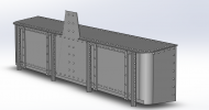
and here's the 3D model

1668895221940.png

It looks very impressive with all the rivets, but I'm far from convinced they are correctly spaced or placed, or even sized, and I am sure that the pattern on the flange that sticks up is not correct.

I think I am going to have to visit Didcot, and measure and model a known vehicle in order to do a proper job of this. At least I'll not be imagining that the designer ' would have spaced these rivets at 3" centres, and those at 6" ' because it seems that that way, madness lies.

I'm going to slice up what I've modelled, print it to have a go of the printer, and live with it until I can get better data - unless anyone has a better idea?

Hopefully, drawings of suitable axleboxes and springs (and brakes) will be in GWRJ or one of my other references, and I can make a decent fist of generating 3D files for them, that will at least make a start on the underframe details.

I have a massive list of things I want to print, so I'm sure I can keep myself entertained. Some are rather less exacting than others (eg wheelbarrows, sack trucks, a fireplace for the signal box) so maybe they will provide some light entertainment, assuming I can get some basic dimensions.

Thoughts and suggestions very welcome
Simon
 

michael mott

Western Thunderer
Looks interesting Simon, good luck with the printing.
I might ask a favor when you are in Didcot ....if they have possibly some info about Dean Clasp Brakes, and if yes could They share it with you.

Thanks Michael
 

simond

Western Thunderer
Morning Michael,

I had not forgotten…. Unfortunately, a Didcot visit is likely to be delayed until the springtime, but I will find those brakes and take photos (unless someone beats me to it)

trust your convalescence is proceeding satisfactorily?

cheers
Simon
 

Phil O

Western Thunderer
Hi Simon,

From memory the rule of thumb was the rivet diameter was three times the plate thickness and the pitch was one and a half times the rivet diameter, I can't remember the figure for the distance from the edge of the plate or the spacing for a double row of rivets.

The info on the web seems to be orientated towards the aircraft industry, not general fabrication work.
 

simond

Western Thunderer
Thanks Phil,

the issue is that there are loads of rules of thumb, and estimates, and “would haves“, and applying them leads to conflicts and blind alleys, so I’ll cut my losses, print it as a test piece, and revise it when opportunity allows. There is a suitable candidate at Didcot, I just need to get my tape measure on it!

the mk2 version will be better than the mk1, and eventually mk3 will supersede it!

cheers
Simon
 

AJC

Western Thunderer
Thanks Phil,

the issue is that there are loads of rules of thumb, and estimates, and “would haves“, and applying them leads to conflicts and blind alleys, so I’ll cut my losses, print it as a test piece, and revise it when opportunity allows. There is a suitable candidate at Didcot, I just need to get my tape measure on it!

the mk2 version will be better than the mk1, and eventually mk3 will supersede it!

cheers
Simon

Brassmasters do a kit (I've built one, the accompanying crane remains in the box): GWR Diagram L4 crane match truck

Lots of detail pictures and pictures of the etches which might help?

Adam
 

simond

Western Thunderer
Thanks Adam, that’s another option, I guess.

Let’s hope I’ll get a nice day at Didcot with the camera, tape measure and laptop and then we’ll have a model that can be scaled
 

Tony Overton

Western Thunderer
Do the Didcot people mind visitors 'getting up close' to wagons around the site and measuring and photographing. What with so many rules today when I visit I'm nervous about looking under wagons and examining stuff else where on stock close up just in case someone spots me and says stop, you can't do that.
 

simond

Western Thunderer
Tony,

my experience to date at Didcot has been hugely positive, to the extent of asking & being allowed to climb on top of a 4000g tender to take photos.

Probably best to avoid school holidays, but asking has always led to lots of help.

The recent SVR visit did have more “keep off” notices, but again, an enquiry led to lots of enthusiastic help, including a tour round the “keep out” areas.
 

Lancastrian

Western Thunderer
Simon,

What are the colour light signals based on ?

I've been busy doing these:
Colour Lights New Ears RH v5.png
Based on the Westinghouse 1955 style of colour light as used on BR(S).

Ian
 
Last edited:

simond

Western Thunderer
Ian

I asked Adrian to move this to my workbench -

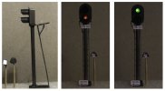
they’re LMS 2-aspect. I was looking for very early LMS ones as John’s layout is set in the early 30s. I found a very useful download on the LMS society website, and worked the 3D up from there. I‘m not swearing that the 3D is really accurate, but it‘s close, and it takes very slightly modified 5mm LEDs and standard signal ladders, and it’s entirely good enough for a working garden railway.

I was chatting with Jon Fitness a few days back, and he suggested SMD leds, behind lenses. I’m sure this would be the way to go if you’re looking for a more hi-fidelity approach. I guess I’d have custom PCBs made for the back of the housing, and fit the housing to that, rather than t’other way about.

The LMS Society - Downloads - the drawings were in the S&T download

If you, or anyone else, want a copy of the 3D files, please ask, I'm happy to share.

I look forward to seeing your Westinghouse ones - I see they have pigs’ ears!

Atb
Simon
 
Last edited:

Yorkshire Dave

Western Thunderer
I was chatting with Jon Fitness a few days back, and he suggested SMD leds, behind lenses. I’m sure this would be the way to go if you’re looking for a more hi-fidelity approach. I guess I’d have custom PCBs made for the back of the housing, and fit the housing to that, rather than t’other way about.

I use SMDs all the time now in both 7mm and 3.5mm HO scale.

And used them when I converted a 7mm BR standard 2 apsect signal kit to a LT version (i.e. rounding the bottom of the back plate). Current limiting resistors are on a separate circuit board for placing under the baseboard.

Signal 06.jpg

Signal 15.jpg
 

Lancastrian

Western Thunderer
Hi Simon,

Yes, the dreaded pigs ears ! What a palava they've been to do with no drawings, only photos and a basic outline drawing.

We'll be using SMD LED's as Dave has for his, and PeterR of our group has sourced some 5mm diameter laser assembly lenses we can use for the opticals.

Ian
 

simond

Western Thunderer
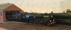
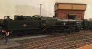
An interesting evening; Will has purchased a couple of very nice toys, a Masterpiece Models Castle, and Merchant Navy. Both second hand, and both very little used. They both have sound, and the MN has a Seuthe smoke unit.

3B02834C-DAD1-4C4D-BA30-A846CDCC7DA7.jpeg0B034D36-BB72-46BC-8D0E-3F49676B332A.jpegF42152FE-7AF8-4A43-848E-4FBC1AED95FD.jpeg6DC46E47-3FC9-45C3-ADB5-5647E3CCA35E.jpeg2F19A88A-B850-4AE1-B208-7C6EC63A787C.jpeg

The Castle has the most horrible steam sounds, though everything else sounds reasonable, if typically at weird volumes - so shovelling is as loud as the safety valves, which is daft. The volume issues we can work through, but the chuff is horrid. After some investigation, we concluded that the chuffs are cam controlled, and the cam and possibly the wiper seem to be somewhat grubby and/or corroded, so I prescribed a good hour on the rolling road, we’ll see if that fixes it. My working assumption is that if everything else is ok, then the speaker, etc, must be ok. It’s just the chuff.

The Merchant Navy sounds very much better, but had an entirely different issue. on opening the throttle, it takes off like a startled fawn. Played with ACC & DCC, improved but still abrupt. Ok, says I, let’s look at the start voltage. It’s set to 5. Set it to 3, better, set it to 2, even better, set it to 1, ah, now that’s nice. Turn the sound on, what’s that? the chuff is very distorted at STV =1, to the extent that it sounds like a diesel. It’s distorted to a lesser extent at STV=2, and not distorted but not synched at 3 & 4, synched at 6 beats per rev from 5 upwards. Not come across such an issue before.

Does anyone in the congregation have any insights?

thoughts are tending towards turning off the cam sensor and manually synching the chuffs via the cv settings, which is what I’ve done with all the locos I’ve built.

they are really lovely models, though. Must up my game…
 

Focalplane

Western Thunderer
If the decoder allows the cam to be replaced by cvs, that would be good. But some decoders don’t have this facility. I found this out when I suggested this to Broadway Limited as a work around for my non-chuffing SP Cab Forward.

Paul
 

simond

Western Thunderer
Thanks Paul, as far as I’m aware, ESU decoders (both locos) do allow for a cv-controlled chuff. I’ll have to read the b… manual though!

just hoping to hear from anyone who has experienced the issue, always easier to learn from others’ mistakes than to make them oneself!

and they are seriously expensive toys, I’d really hate to do something expensive…
 

LarryG

Western Thunderer
Cam controlled exhaust must be best. Setting sound to wheel revolution drove me mad because it went out of sync as the loco accelerated. Only Digitrains Zimo sound decoders were reliable in this respect.
 

simond

Western Thunderer
Hi Larry,

I’ve used Zimo on most of the locos I’ve built, and am very happy with them. A couple of earlier locos have ESU, no complaints either. The technique that I picked up (Zimo manual perhaps, can’t recall) was to get everything running really sweetly, then get the loco going at speed step 1, or at least very slowly, and adjust to get synch then. This is usually a faff, but worth sticking at. Then there is another cv that gives synch at a slightly higher speed, and above that you don’t care because your eyes and ears can’t tell if it’s in or out.

As long as it’s credible when starting or slogging, it’ll be fine when galloping. And drifting steam, clanking rods, it’s less critical anyway.

cheers
Simon
 

Focalplane

Western Thunderer
My Lee Marsh Jubilee has a three cylinder cam fitted to one of the driving axles, but I was surprised to find that it isn't used! CVs are used instead. Although 45688 and others are in use all the time, I would guess that most "museum quality" models are rarely run but sit in show cases.

The older decoder fitted to my Cab Forward does use a reed switch adjacent to a small magnet on the flywheel. When iit stopped working I finally found that I could "force" the reed switch closer to the flywheel using sticky tape! And it worked. Particularly important for an articulated two engine loco as the beats go in and out of phase all the time. When things get warmer and my viral problem finally clears up I'll do a demo on my HO thread. Can you adjust the proximity of the pick up to the cam?

Paul
 

simond

Western Thunderer
Hi Paul

the cam on the Castle actually wipes a sprung contact, it’s not a reed switch, and my suspicion is that the cam and spring are not a clean as would be ideal.

Let’s see how Will does with it on the rolling road, as apparently, the previous owner didn’t get much/any use out of it, according to his widow who sold it to the dealer from whom Will purchased it. I’d guess it’s been out of the box a dozen times and run less than 15 minutes.

will report further in due course.
Simon
 
Top