A Layout Called CHIMTONSTOKE

LEVER FRAMES
  • David Waite

    Western Thunderer
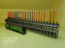
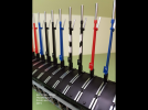
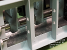
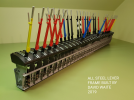
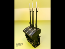
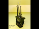
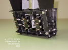
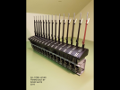
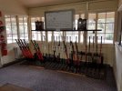
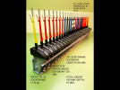
    I will start with a description of the 3 All Steel Lever Frames that I built in much of my spare time over 3 years and finally finished them in 2019. They are of no particular prototype but a combination of many, a sketch was drawn up to give good proportions and sizes inc radius, tapers ect other than that they were just built through my minds eye as I went along. The smallest is a 3 Lever Frame for the control of points at WAITECOTT branch station, the next is a 15 Lever Frame, levers 1 to 14 will control the points at the loco depot and lever 15 will control the Locking on the Turntable. The largest frame is a 30 Lever Frame this will control all point work and all running signals including two Detonator placers at PINE OAK JUNCTION this frame will be fully mechanically interlocked.
    All the components were made by hand and machine or combination of both, various grades of steel including Stainless steel were used, the only non steel item used and the only item I didn’t make other than screws, nuts , springs & pins ect were the etched brass Lever number plates that I purchased from DCC Concepts. Many jigs were produced as required to hold the various pieces when being made to give a uniform build quality and positioning .
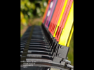
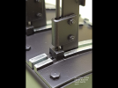
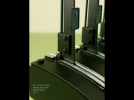
    The Lever Handles are 304#SS turned & slotted and then 45%silver soldered to their Mild Steel (MS) Lever the Catch Handles are 410#SS (high tensile) and are 45%silver soldered to their MS-U bracket. The Quadrant sections are Bright MS milled, I then made a die and pressed them into shape at 4000 psi each to give them all a uniform shape including the spring back these were then Blue Zink plated “by others“ to prevent the bare metal guides that the catch block slides along from rusting.
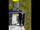
    The main shaft is 5mm dia 304#SS, each lever has a bush 45%silver soldered into a extension piece that is spot welded to the bottom of its lever there are two floating bushes between each lever on the shaft to eliminate any friction the total end play of all levers inc bushes after assembly on the 30 lever frame is .005” this gives a perfect centre position of each lever between its two adjacent quadrant sections. The Clevis pins on the catch handle are tempered pins and are 0.9 mm dia the catch rod is plain mig wire flattened and drilled at the end to suit the pins the catch block is attached to this rod by 45%silver, this rod assembly was then pickled and copper coated to prevent rusting from the flux, the spring block that is attached to the lever is only acting as a guide as the spring assembly is below the quadrant as you will see in the photos, I think I’ve covered the main sections which wouldn’t have been known unless told hopefully the photos will load, if all goes well I will add to them over the next few days.
    AFAF3E37-E963-4705-B17F-DB0376460C1D.png
    DCF596B3-EB95-45AF-AE4F-5DCA226C11F6.png1D0AFBEE-C08B-4C4B-8EC4-162505AC2975.pngEEFF8CF9-D960-4398-9C13-EFD58C680A94.pngA9B6E637-9102-4F84-9032-4694033DFDB1.png361DE630-7D06-4209-802F-782A373B615A.png77E1D5AB-4F56-4321-A635-43C96DFC40FE.png14236CAC-FCD0-4EEE-9B74-DA7968F7743C.png23554F73-764F-4DF1-A9A2-E4964A49B830.png9AD7CC71-DA4F-4705-A1D2-74AE88A5FC84.png4AC1959A-CDE7-4E60-8CA9-D95BD2318551.png5206FE9D-3077-4203-9DFD-4C7D42F28F97.pngC5B502A2-1643-477E-969D-55352C0C0EE6.png94B83F9F-E3DD-472A-A300-69B0772A050D.pngADB04E0F-CF14-4D2A-A83A-AC7A2D6D7A5A.png318D65A5-0E64-4426-942F-3E418D5A3F5C.png
     
    MOVABLE CONTROL PANEL
  • David Waite

    Western Thunderer
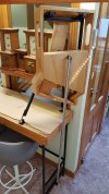
    This next section is about the construction of the movable Loco Yard control panel.
    I lost many of my Digital photos at one time but luckly I had some made into prints before this happened so some images are scanned I apologise if they appear a bit grainy.

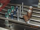
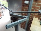
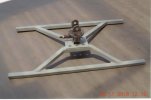
    This photo shows the bearings and their housing tubes that will be welded to the ends of the arms.
    DSCN4739.JPGThe finished and assembled arms

    DSCN4851.JPGThis photo shows the arms fitted to the support frame this frame will be attached to the legs of the Base Board, the free end of the arm is where the Tilting Head piece is attached to. DSCN4853.JPGConstruction of the Tilting Head Piece.
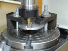
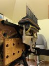
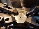
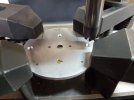
    This photo shows one of two identical size discs, this one having a slot the other disc has a hardened pin fitted that rides in this slot this gives a limited amount of twist to enable horizontal levelling of the control panel when needed.DSCN4961.JPG
    These discs are compressed together by a spring under compression that is hidden inside the rectangular tube that is attached to the slotted disc in the photo this gives friction to the discs to keep the control panel firm and in place.
    Scan 2.jpeg
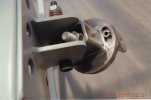
    This photo shows the tilting compression spring that gives friction to the control panel as it's moved from vertical to the horizontal position and holds it at any given position.Scan 1.jpeg
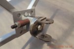
    Here is a rear view of the frame that the control panel is mounted to, in this photo there are still two more brackets to be welded to the slotted disc which is the lower disc in this photo, these brackets are what the two aluminium arms are attach to which keep the Lever Frame horizontal at all times. Scan 6.jpeg
     
    Movable Control Panel
  • David Waite

    Western Thunderer
    The completed assembly in the vertical position, there is still a metal cover to be made which will cover and
    protect the underside of the switches and wiring on the Lever Frame this cover will also have rubber buffers
    attached at the rear of it to protect the edge board on the layout.
    IMG_8038.jpeg

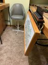
    In a tilted position. The chrome thumb screw that can be seen holds the Control panel in place the panel
    is hinged along the lower edge of its support frame.
    IMG_8037.jpeg

    The next 3 photos show its movement from vertical to horizontal.
    IMG_8057.jpegIMG_8056.jpeg
    IMG_8055.jpeg

    Facing towards the South.
    IMG_8058.jpeg

    Facing towards the North

    IMG_8063.jpeg


    IMG_8064.jpeg

    Can be turned on almost any position and angle.
    IMG_8068.jpegIMG_8069.jpeg

    The panel is shown in its lowered position for access, the pink string isn't permanent there will be 2 small
    chains when finished, there is also a rear ply cover that will be fitted to the rear of the Panel when finished as
    seen in the next photo
    IMG_8048.jpegIMG_8042.jpeg

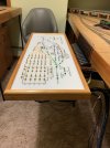
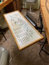
    The panel face was made for me in the mid 1990s from a drawing I did. It is a laminated two piece sheet, clear on white Perspex, all the lines and text was milled through the white rear sheet and slightly into the clear face sheet then paint was applied into the recesses its held to a timber backing by all the switch lock nuts across its face.
    IMG_8045.jpeg
     
    4mm BALANCED type TURNTABLE with Cowans Sheldon, Vacuum Tractor.
  • David Waite

    Western Thunderer
    I built my TURNTABLE in 1987 but the seed had been sown back in September 1980 when I picked up the latest edition at the time of Model Railways which had this entire edition dedicated to Frank Dwyers Borchester Market. A few things I read about his layout inspired me, One was working signals , Two was hand made track and Three was to build a turntable that was accurate in its operation.
    My TURNTABLE is based on the LNER type ( Kings Cross ) but I have put the Vacuum Accumulators above the decking not underneath.
    The only way I knew to make something accurate and solid was to build the pit out of STEEL so I did, I weighed the complete TURNTABLE assembly the other day and it weighs 12.6 Kg that's not a Typo that's 27.78 Lbs.
    The pit base is made from 10# Black Iron (1/8"thick ) this I Gas Axed out of a square sheet to a dimension slightly larger than needed to allow for the pit wall to sit on and be welded to , immediately the disc dropped I poured cold water around its outer edge this causes the disc to shrink and take on a concave shape. A strip of 10# was cut for the pit wall and a thin strip was cut and curved into a circle for the top lip this supports the Pit on the Base board and is what the Coping and the outer ring of timber walking boards are fixed to.
    The welding was all done by Ark there were 12 / 2.5 mm electrodes used in total, the pit wall was tack welded to the disc complete with the Table access service hole then the top lip tacked welded to the wall then fully welded with no distortion within 1mm when cooled. I was able to use any machinery after hours where I worked so long as I put everything back as I found it ready for the boys in the morning, one evening with the aid of the crane I swapped over and put a four jaw 2' chuck onto the 12' MAXSON lathe, I turned the lip and pit wall and machined a flat section on the disc near the base of pit wall for the pit Track Rail to be soldered to and machined out the centre hole, I then reversed the pit on the chuck and machined off a flat section on the underside around the centre hole for the bearing housing to be mounted against and then trimmed the disc edge and machined the underside of the lip.
    The Table girder frame is made from 0.012" tin plate with brass sections soldered on to finish it off, the decking is Balsa wood and hand rails are brass. The Code 70 rails are soldered to small pieces of copper clad which are fixed to the cross beams. There is a Collet soldered to the centre section between the main frames which clamps tightly to the hardened main shaft this is hollow for some of its length for the rail wires to be fed through. The 2 Table locking Levers are movable and are made of brass and the Angle Iron slotted guide mounted on the decking is made of four sections all mitred and soldered together, the push levers are brass and also move and can be folded back against the deck or left in any position. The two Vacuum Accumulators are brass with copper ends and soldered together and considering when welding something that becomes sealed when cooled a partial vacuum is created within ( smile ). The concrete dome on the pit base under the centre of the table is Tin Plate soldered in position with the drainage around its edge.
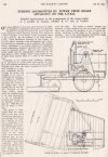
    Our State Library had at the time many publications one of which was the Railway Gazette a must to read, I searched the details of the Cowans Sheldon Vacuum Tractor that was patented by them this was first applied to the Kings Cross Turntable in 1933, improvements were made and I have modelled the improved one of 1936. Photo copping was not allowed but the library would Micro Film any page that you listed down for a small fee which took a couple of weeks and they would also print off copies from the film which they did for me.
    The tractor is to scale and uses all the correct shaped brass metal sections underneath which cannot be seen, it's hinged to the table and rocks if you push down on the decking and flex table. The Vacuum Engine Cover is Tin Plate with brass sections soldered to it, the Drive wheel under the Tractor is made from plastic with a plastic gear attached to the side of it and the piece of rag in the mans hand is paper.
    David.

    Bit of history.
    Scan 22.jpeg


    Scan 23.jpeg

    This next drawing is the one I have Modelled.

    Scan 11.jpeg
     
    BLOCK INSTRUMENTS
  • David Waite

    Western Thunderer
    In 1996 I built by hand and finished and installed 6 fully working BLOCK INSTRUMENTS [ 3 pairs ] they are based on the WINTERS BLOCK Single Wire Two Position DOUBLE LINE INSTRUMENTS.

    History
    Siemens Bros LTD were the builders of the Block Instruments that were patented by George Kift WINTER of the Madras Railway Company [INDIA] in 1880.
    Fifty of these were originally purchased by the Victorian Railways [VR] in 1883 however they found faults with the original design which were caused by the timber warping that the mechanism was mounted on so Brass castings were made along with other alterations to improve their operation, from the original Two Coil Instrument to Three coil in 1888, the Commutator was also removed from the side of the Instrument and placed on the Centre front. The original Instruments were for Single Line use VR modified the design for them to become DOUBLE LINE Instruments these lasted in operation on the North East Broad Gauge Main Line up to a couple of years before I retired I think it might have been around 2019 or 2018 it was the Copper wire theft from the telegraph poles that finally put them out of action after around 130 years of operation.
    The Instruments only use Power when being used so battery life is long when I started with the rail they were run by one 6VDC BIG JIM or EVEREADY Dolphin battery, towards the end they were run from the mains supply with a globe in series for short circuit protection.

    The 6 Instruments I made are Two Coil Double Line Block Instruments they each stand 17" tall they work as the Prototype dose, they can also control Starting Signals if I wish to do so, my wife helped me to wind all 24 coils of fine Enamel Copper wire which is certainly a job for two people. They look nothing like the Winters Instruments they are of my own design, the First reason for this is I don't have the space on the Block shelf at Pine Oak Junction so the UP & DOWN needles on each Instrument needed to be one above the other not side by side all the UP LINE Needles are at the top of each Instrument the DOWN LINE Needles are underneath, the Commutator for each has a brass plate with UP or DOWN stamped on it so you know which needle it is for in any case the UPPER needle UP LINE , LOWER needle DOWN LINE simple. The second reason for their design is I wanted something that looked a bit British and the WINTERS dose not in my book. The casings are made from pine and have weathered the last 27 years of vast temperature changes very well, it is 38C out side at the moment and a nice 29C in the attic as I type this come winter it will drop to 10C or less. Each Pair of Instruments has a matching Bell sound from LOW , MEDIUM to HIGH the High sounding Bells being CHIMTONSTOKE to PINE OAK Junction , Medium sounding Bells being PINE OAK junction to COALCHESTER , and Low sounding Bells from PINE OAK Junction to BRIDGETON.


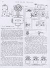
    This is a scan I did from my book of POWER RAILWAY SIGNALLING by RAYNAR WILSON printed I believe 1909
    it shows the original Patent with the Commutator Handle on the left hand side .

    Scan 25.jpeg


    This Photo I took at Kilmore East showing the Instruments in their final design they were in full daily working order shown here about 10 years ago. The grey box on the wall next to number one Lever that has a power lead plugged into it is the power supply for the BLOCK Instruments.
    As can be seen the Commutator handle is in the front above the Tapper Key and between the two Needles.
    20190219_125656.jpg
     
    DOUBLE LIFT UP SECTION
  • David Waite

    Western Thunderer
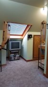
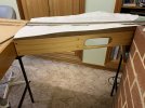
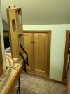
    My Baseboards have Two walk through areas one has a Single Lift up Section the other is a Double Lift Up Section one half is Automatic the other is manual reason for it being Double is I need the open space with both Sections up in the air to have a unhindered view of my Television which is under the roof window and also gives a bigger open area to walk around.
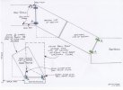
    I have drawn a sketch of the Two Sections to accompany the text which will show and explain the design better.
    The Automatic side [ Motor Driven ] Butts to its Base Board squarely so normal hinges shown as Hinges A [ in Green ] could be used.
    The Manual side is Different the Base Board on this side is square however the Manual Lift up Section that connects to it runs off on an angle from the Base Board end so if normal hinges shown as B [ in Blue ] were to be used the Lift Up Section would rise on a angle and block off half of the walkway as shown on the sketch, so I came up with a way of making the Manual Lift Up Section rise in a upright position using Automotive Suspension Ball Joints shown in Pink on the sketch. These Ball Joints can pivot in any direction which is what is needed as the arm that connects to the lift up section not only pivots in the way a hinge dose but also Twists as the Lift up section moves from horizontal to its vertical position.

    Scan 24.jpeg


    The Lift up Sections are made from Pine with Steel frames incorporated into their design to give strength and keep them true the actuating arm from the Drive Gear box also connects to the Steel frame on the Automatic side, the Hinges on the Automatic side are fabricated from steel with Ball races as the bearings and are connected directly to the Steel frame. Where the Two Section meet there are Dowel pins to keep side way movement within a couple of Thou these pins locate into slots that can allow opening movement of the rail gap for expansion of the two sections which is minimal throughout the year.
    20200514_162057.jpg
    20200514_161707.jpg

    20200614_155237 (1).jpg
     
    SINGLE LIFT UP SECTION
  • David Waite

    Western Thunderer
    The other access near the chimney only needed a Single Lift up section however the small walk through created a couple of issues that needed to be overcome to make it user friendly not just for me but also the railway.
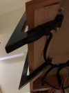
    Firstly the Lift up Section needed to lift and move over the top of the board it is attached to so the walk through gap isn't reduced by the thickness of the lift up section when it is in the vertical open position, this was achieved by making under slung hinges these are made from 20mm 20mm RHS, the hinges are also level with the base board surface so they don't get in the way of the track work. I seen this type of hinge many years ago in a magazine and never forgot it. By using RHS the cabling can be put through them neatly and out of harms way.
    The second issue is that Clothing could get caught on the Protruding rail ends as you walk through the gap however that was a easy fix, the following photos will tell the story.


    IMG_8746.jpeg


    IMG_8715 2.jpeg

    As can be seen the Lift up Section is completely clear of the walk way, its over centre of weight keeps it upright.
    A piece of Timber is still to be fitted across the two vertical sections of the hinges this will protect the rail ends on the base board
    and allow one to slide past and not get caught up on the hinges.
    The single track on the Lower Left is the Branch Line to WAITECOTT.
    IMG_8717.jpeg

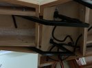
    Under side view in the Raised Position showing the cabling entering the RHS to the Rails.
    A solid piece of square steel is fitted into the ends of the RHS this has a steel pin as a pivot and is fitted into the other half
    of the hinge which is bolted to the base board.
    IMG_8720.jpeg

    In the Lowered Position
    IMG_8721.jpeg


    The Rail End Protector this is lowered by the Lift up Section pushing down on it as it as the Lift up section is lowered into place.
    IMG_8730.jpeg


    The next 3 photos show the Rail End Protector being pushed downwards and out of the way.
    IMG_8725.jpeg


    IMG_8726.jpeg


    IMG_8727.jpeg


    There is one spring that pulls the Rail End Protector up wards the spring tension is only strong enough to do the job and a little more
    it doesn't interfere with the Lift up Section this being just to heavy with the plaster on it
    IMG_8722.jpeg
     
    Sykes Brass SR Signal Arm Repeater Instruments
  • David Waite

    Western Thunderer
    There will be some Signals that will be out of view from the PINE OAK JUNCTION Signal Box so these signals will need to be repeated by Signal Arm Repeater Instruments on the Block Shelf, there will also be some Signals that won't exist such as Distant & Outer Home Signals as my layout would need to be huge to accommodate them however these will be represented by Signal Arm Repeater Instruments. The Lever Frame and Interlocking for these Signals will be in fully working order but instead of operating a Signal which of course won't exist it will work a Repeater Instrument which would be required in any case being completely out of view from the Box.
    I require 9 Signal Arm Repeater Instruments in total the first 6 of these I have modelled to represent the Sykes SR brass type of Repeaters these are slightly over half size at 65mm or 2 9/16" in diameter the prototype ones being about 4 1/4" in diameter I believe.
    There were a few things that governed the final size of the repeaters first being the space I had to mount these Repeaters on second being the internal size of the mechanism that operated them and third being the casing infact this is what finally gave me the deciding factor.
    Having never seen a real one other than in photos I drew up a sketch of sizes and proportions that I worked out from the many photographs I collected and then built them from my minds eye as I went along, it took me 4 months to build all 6 of them and install them in their final position under the Block Instruments.
    I will explain how I built them as I post the photos of their construction.


    I cut the 6 Face discs out of 5mm Aluminium with the boring head the reason for the use of Aluminium is because its non magnetic.
    20200829_162845.jpg


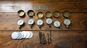
    The size of the Repeaters / discs were finally governed by the casing size I had old Oxy & Acetylene gauges from my working past that I realised their casings would suit the purpose well so these were quickly pulled apart, in the photo are old tap spindles these became the source of brass for the bridge bearings
    20200830_130612 (1).jpg


    The discs were put into the Lathe centre drilled and the outside diameter finished off then the scratches on the face of each disc were sanded off as shown in the photo the sanding was done a couple of times throughout the build.
    20200903_161257.jpg

    The holes are accurate the lines are not they are just there to keep me in check, my eyes are failing faster than I would like these days so I purchased a DRO for my mill drill as I find it hard to read the rotating scales, not only that the metric scales all read different and I tend to get confused easily these days so the DRO has made a world of difference I can now see the numbers on a digital readout so me and my mill drill has a new lease of life.
    20200921_111308 (1).jpg


    Counter sinking for the screw heads
    20200921_121411 (1).jpg
     
    SIGNAL BOX DIAGRAM for PINE OAK JUNCTION
  • David Waite

    Western Thunderer
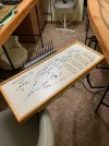
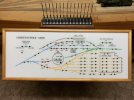
    The latest project for my layout is a Signal Box Diagram for Pine Oak Junction, it is all hand drawn and coloured using water colour paint.
    This project is something that I had been thinking to do for sometime but could never find the right time to start, after the six Sykes Instruments were finished and then the 3 mechanisms for the next repeater instruments were done my mind was clear to finally begin.
    The drawing of this Signal Box Diagram, was for me a personal challenge I knew in the back of my mind I had the ability to draw it even though I had never done the likes of it before, the challenge for me was being able to see.
    The world now days is blurred for me without my glasses, these allow me to see only the day to day things and because of things called floaters inside my eyes I miss out on random portions of my vision, however I have a magnifying head piece that can hold two magnifying clip on lenses of different powers which I can wear in front of my glasses, I change different lens powers depending on what I'm doing with this I have been able to accomplish many things like the Lever Frames & Repeater Instruments it wasn't easy but I got by.
    The drawing of the Diagram has a lot of free hand involved which isn't easy when one cannot see good, the first stage was drawn in pencil this was ok as mistakes and alterations which there were many could be rubbed out, however it became nerve- wracking when I had to ink over all the pencil lines with a permanent ink as a mistake could not be removed so what ever I did I had to get it correct the first time only.
    I met this challenge with a open mind and I'm so pleased with what I accomplished I started the project in March 2022 and finished it on the 13 March 2023, I worked on it bit by bit when ever I had time throughout the year, there were of course other things involved with the making of this Diagram that also took up some of this time.


    The Signal Box Diagram.
    My favourite style of Signal Box Diagrams are the ones that were drawn in the 1890s and some up to around 1910 these are the years which my one is based on. Most railway companies and railway signalling contractors from my own observations tended to copy each other within periods of the railways history, diagram styles changed over the years due to the design of the older Diagrams not being able to cater for modern equipment that was part of a more modern railway.

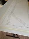
    It took me each night over 3 weeks to sketch a shape of a plan that reflected the overall shape of the track work in a simplified way, many pieces of paper were consumed over this time. I made a drawing board many years ago but the top was too small so I attached a piece of melamine big enough to do the job on top, to this I sticky taped down some tracing paper which was the same size as the Diagram I wanted allowing for a margin and the timber frame, the frames outside dimensions are 995mm x 440mm with a face width of 40mm
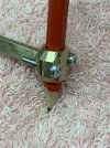
    After copying the sketch from the paper and increasing its size onto the tracing paper I released I needed a compass that could draw a radius of up to 300mm, my old Staedtler could never do that and what's more the compass needed to hold a pencil that used a 0.3 mm lead and also the tapered casing of a permanent ink pen so the solution for this was to make a compass.

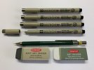
    The Ink pens and pencil I used.
    The Pigma Micron are an Archival permanent fade proof ink pen the clamping area has a slight taper.
    The 0.3 lead pencil is parallel but slightly larger in diameter.
    IMG_E9376.jpeg


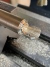
    I turned up the pen clamp in the lathe then cut it in half then finished it off in the mill.
    IMG_3746.jpeg


    As can be seen the screw holes just made it, the diameter of the stock was the largest I had but it worked out ok as
    the size of this clamp had a nice feel to it when the compass was being used if it hade been any larger it may have been cumbersome.
    IMG_3747.jpeg


    The two Philip headed metric screws worked a treat I thought they might have been a nuisance to use but they worked prefect.
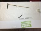
    The flat rear view of the clamp is where the long Radius Arm is silver soldered to this arm is made from a piece of 6mm x 3mm brass 530mm long it has 43 x 3mm indexing holes drilled along its length at 10.0000 mm centres these indexing holes is what a locking pin on the sliding assembly locates into. This sliding assembly has the needle and its fine adjustment to move it and lock it at any position between each pair of indexing holes along the length of the radius arm.
    IMG_3748.jpeg


    IMG_3750.jpeg


    The clearance around the screws allows the brass clamp to follow the taper of the pen and tighten without movement.
    IMG_3754.jpeg


    The clamp attached to the Arm.
    IMG_3842.jpeg
     
    Drawing of the SIGNAL BOX DIAGRAM
  • David Waite

    Western Thunderer
    Now that the Compass had been made I could continue on with the Diagram.
    The reason for the use of the Tracing paper for the trial sketch was only because it is easy to remove mistakes with an Eraser so nothing to do with tracing. The Compass worked a treat, it took many attempts to get the sketch correct as allowance had to be made for the the Signals to fit as these are 46mm long with a spacing of 25mm and so both junctions were moved a few times as well as the alignment of the main lines and naturally the radius of all the tracks changed slightly each time for both, as each radius was done I circled the Needle hole with a pencil and wrote the radius next to it.
    When I was finally happy with the track work I cut up pieces of thick card and taped it over where the Needle point holes were, I then went over each radius again with the Compass and once correct I pushed the Needle into the card leaving a new Needle point hole, now that I knew these card pieces worked and maintained the correct position and without the Needle point going through them I removed these small pieces of card and replaced them with better ones, some of them I replaced with longer ones these were taped firmly to the drawing board away from the tracing paper and laid gently across the top of Tracing paper with a new Needle point hole placed in them at the correct position.
    The idea behind this is so I could un tape the Tracing paper and slide it out from under the card and replace it with the Digram paper by sliding this back under the card pieces.
    The other reason for the card was to prevent any holes being put into the final Diagram drawing

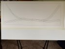
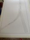
    This shows the completed sketch in pencil [0.3mm] and the test pieces of card for the pivot positions of the Compass
    IMG_1994 (1).jpeg

    The paper that I used for the Diagram is made in France by ARCHES its a Hot Pressed 360 gram Acid free Cotton Fibre paper, I chose this thick paper to help prevent any buckling of the Diagram from the likes of moisture.
    I didn't take any photos of the Diagram with only the pencil lines as they didn't show up very well on the white paper.
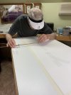
    In this photo I am slowly Inking over each pencil line with the permanent Ink pen trying to keep my shaky arms still, this kept my nerves on edge I was glad when it was done, in this photo most of the card pieces have been removed as the lines were done and they were no longer needed.
    IMG_4685.jpeg


    First major stage done.
    IMG_4688.jpeg


    IMG_4689.jpeg


    IMG_4690.jpeg
     
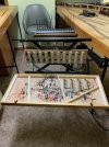
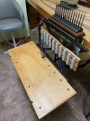
    Frame for Pine Oak Junction Signal Box Diagram
  • David Waite

    Western Thunderer
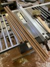
    I hade two attempts at making a frame, my first attempt was making a frame out of a piece of Mahogany that I had, it was wide enough but its ruff sawn thickness was not much more than the finish size I wished for, however I decided to machine it up to see if it looked ok once it was finished, but no it looked to thin and was out of place so this will get turned into a frame for my wife to use.
    I started looking in amongst the timbers that I have not expecting to find anything but lo and Behold there was a piece of Merbau about six feet long standing hidden in a stack. I measured it up and allowing for the blade thickness and minimal machining it would do the job nicely.
    Merbau is a heavy timber, its used nowadays as a replacement for Jarrah [ but its not as good as Jarrah ] and used for window sills Door sills and Decking.

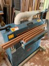
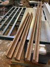
    The piece of Merbau was cut into four pieces squared up and trimmed almost to size in the Thicknesser, it was then run through the Drum sander to give the final size and a smooth finish, it has a tendency to char the fine belt due to the oil in the timber however it doesn't affect the course belt.
    Squared & finished to size.
    IMG_7910.jpeg


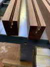
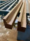
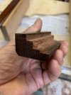
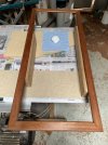
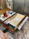
    The frame isn't made as a normal frame would be made I have rebated [ stepped ] various levels, First the glass, Second for the 3.8mm matt board spacer & inc Diagram with its 3.8mm Matt board backing and Third for the rear 3 ply backing.

    First stage of the Rebating done on the table saw.
    Those slivers are just less than one mm
    IMG_7913.jpeg


    IMG_7911.jpeg


    IMG_7914.jpeg


    IMG_7916.jpeg


    The end result
    IMG_8524.jpeg


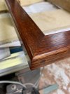
    Like normal I got so caught up in the build I forgot to take photos of the assembly, the corners are just Butt Mitred glued joints however my research has turned up various ways these corners were held together some simply nailed through the end sides, some with a wood screw entering through the end sides and some with a metal bracket as a extra hold at the rear of each mitred corner. There are of course other ways that the corners were made such as Mortise and Tenon ect but I'm only concerned with the Mitred joint type.
    IMG_8073.jpeg


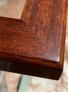
    From the outset I wanted to French polish the finished surface which I did, this is done with many thick grain filling coats and many '30 plus' thin finishing coats of amber Shellac this was done to the sides and both chamfers of the frame only and are to a mirror finish.
    The face surface has no grain filling but the fine sanded flat finish on it has 31 coats this gave a contrast to the sides and it prevented the face from looking fake [ its the only way I can describe it ] I was very pleased with the result.

    Slowly applying the Shellac.
    IMG_8467 2.jpeg


    The open grain of the Face surface can be seen in this photo, many of the smaller grains filled but the larger ones remained which is what I wanted.
    Merbau has Sliver streaks and with lots of other shades/colours that are richly enhanced with the Shellac.
    IMG_8491.jpeg


    As can be seen I used wood screws to hold the corners which some frames had, of course I don't really need them but they look good and at the same time gives an extra holding force.
    IMG_8496.jpeg


    This photo shows where the rebates are positioned on the under side of the frame.
    IMG_8522 2.jpeg
     
    Last edited:
    A NEW CHALLENGE IN LIFE
  • David Waite

    Western Thunderer
    Well this new thread title above says it all,
    At the start of this year I up dated my glasses, I had new lenses made complete with new frames but by mid May I could not clean the
    misty haze off the new left lens no mater what I used, however it wasn't a grubby lens a trip to a Ophthalmologist confirmed I had lost vision in my left eye, apparently my eye is working as good as the other but the jelly like substance that makes up the eyes inside has failed and cannot be repaired so every thing I see through my left eye now is blurred, But I'm not giving up I have repaired and built things all my working life its what I'm all about, it was once my job that I earn't a living from and now I put my skills to home maintenance and my hobby I'm lost without tools they are my life. So since mid May I kept out of the shed and concentrated on doing day to day things like walking up steps without tripping forward and general maintenance things around the house that didn't require good vision to do and of course learning to accept what has happened this I can say I have done, I have accepted it as one must, WT has been a important link to my hobby its been a struggle to find and post photos but it has been a driving force more than you could imagine.
    Two weeks ago when I decided to have ago at making the spacers for the rear of the Diagram Frame was the first time I had gone into the shed to make anything since May, working the lathe was second nature no problem I'm so glad the dials are metric and imperial I was bought up on IMP and they are so much easer to work and see which is important to me now, each IMP division is a thou the metric divisions are .003 / .002 and .015 on the metric scales on the Lathe and Mill so simplicity is the key, I fitted a RDO on the mill sometime ago so I don't have to look at the hand scales anymore other than the down feed, the biggest problem I found was lighting I need to put extra movable lamps on the equipment.
    I found I have to get so close to the job now safety has become a concern in fact I had to remove a handle off the mill so I could get my head in closer to see what the cutter was doing with my glasses and magnifier head piece on its about 4" from the cutter to see clearly.
    Am I making anything, yes I am so pleased to say, I have a few jobs on the go, One, is to modify and improve my dust extractor so I can make the Timber casings for the 3 repeaters that I have made, which are still sitting in a box. Two, is the making of metal oval Number plates to indicate which signal each Sykes repeater refers to. The final item was a spur of the moment thing about a week and a half ago I was watching a IRSE video about Stick relays that were mounted to the rear of block instruments and their operation, the chap had everything working for the demonstration including two Repeaters one was a RE THOMPSON Track Circuit Indicator, seeing it working I thought I know how to make that but will I be able to and at what average of build quality. Well I have started and I'm doing pretty good considering, I have made mistakes not judging distances and clipping the cutter on the job all eye sight related problems which has made me take a step back and rethink my movements anyhow,

    Here is my, RE THOMPSON GWR TRACK CIRCUIT INDICATOR / INSTRUMENT NUMBER 10.


    Trying to scale up and draw this sketch from photos took me days my right eye gets very tired after a short time, I know there will be many if not all dimensions not to scale with each other but as long as the overall finished item looks convincing I will be more than happy,
    IMG_9825.jpeg


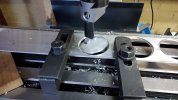
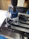
    The Face plate is 4.6mm thick Aluminium, the hole saw seen here is 75 mm Dia.
    IMG_9827.jpeg


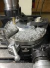
    To bring the diameter down to the required size I used the rotary table the sections un cut under the clamps I filed down by hand.
    The outside Diameter of the instrument casing is 70 mm with 1mm wall thickness so this disc is a little under 67 mm .
    IMG_9831.jpeg


    IMG_9832.jpeg


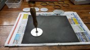
    I lapped the surface using this old valve grinding tool that belonged to my father the suction cup has been replaced many times by me but the handle is original from the 1930s .
    IMG_9834.jpeg


    This is the start of the front bearing its the second attempt I ruined the first.
    IMG_9848.jpeg


    IMG_9841.jpeg


    I used 1200 W&D to remove the cutter marks, the fine marks left by the machining on the original instruments change directions
    on the bearing face, the bearing end which is the highest has the machining lines running lengthways with the bearing the lower
    mounting section has the machining marks cross ways I've tried to do the same.
    IMG_9853.jpeg


    The second attempt lived.
    IMG_9851.jpeg
     
    Terminal Contacts for the Double Lift up Section
  • David Waite

    Western Thunderer
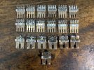
    Before I make a start on the track work I wanted to have the Contacts in place that join up the various power cables that come from the base boards either side of the Double lift up section, at the hinge position of each lift up section the wires will just loop down and flex as the two sections are either lifted or lowered but where the sections meet in the middle a row contact terminals are required.
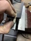
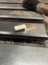
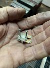
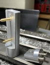
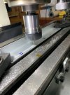
    I had kept all the contacts that I removed from the Relays that were used for the signal instruments, the first thing I did was to un solder all the wires from them the next was to drill and tap M2 threads for their mounting screws as shown in the next photo.
    IMG_0842.jpeg


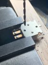
    So I didn't drill into the plastic insulator or damage the terminals I pushed a scrap piece of metal between them and the drill bit .
    IMG_0841.jpeg


    S/S M2 Allen screws
    IMG_0851.jpeg


    The contacts with the heavy terminals will be used for track power the others for Points, Signals and track circuits the Double Lift Up Section will have a total of 38 Terminals.
    IMG_0856.jpeg


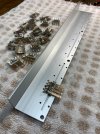
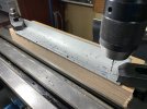
    All the Contacts are mounted on a piece of Aluminium Angle the slots being cut are for the ends of the two small rivets that protrude
    on the underside of each set of Contacts to sit into, this Contact Terminal strip will be mounted on the Automatic Lift Up Section side.
    IMG_0880.jpeg


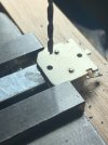
    The clearance holes for the M2 screws being drilled.
    IMG_0882.jpeg


    Testing the fit.
    IMG_0889.jpeg


    I'm not sure where this piece of Fibre Board came from I think I picked it up back in the 1980s so it just goes to show don't through things away
    some day it may get used and in this case it has, its about 1/4" thick with some holes here and there but I managed to dodge them all.
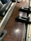
    Each of the Milled slots are for Brass Terminals to fit firmly into these line up with the Contacts on the Aluminium Angle, there are two machined pieces of Fibre Board that will sandwich the brass Terminals and holed it all together.
    IMG_0892.jpeg


    The big Black thing is the nozzle of the Vacuum Cleaner to remove the dust, I thought the Fibre Board might have taken the edge off the Milling cutter but it didn't even though its such a hard wearing product the Cam shaft gear on my Holden is made from this and the long Vanes on the Ammonia rotary boosters were also made from the same.
    IMG_0893.jpeg


    All the slotting completed.
    IMG_0897.jpeg
     
    The Adjustment Linkage
  • David Waite

    Western Thunderer
    The Aluminium Angle that the contacts are fitted to needs to move so the tension of the contacts touching the brass terminals
    can be altered. The Aluminium angle pivots on its mounting screws near the contacts so the rear of the Aluminium angle needs to be lifted or lowered which moves the contacts up or down so an Adjustable Linkage needed to be made.

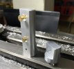
    The Aluminium stock is 38mm diameter this is the mounting piece being made for the Linkage to be attached to a timber on the lift up section.
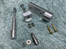
    IMG_1417.jpeg


    On to the Mill for the next stage.
    IMG_1418.jpeg


    The next two photos show the finished pieces in different positions the smaller piece in this photo attaches to the Aluminium angle
    IMG_1453.jpeg


    IMG_1437.jpeg


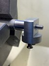
    This piece is being made from Stainless Steel
    IMG_1456.jpeg


    The Aluminium piece pivots on the SS journal with almost no tolerance the journal protrudes slightly from the
    Aluminium piece so when the washer and nut is fitted the Aluminium piece has a little side ways movement on the journal.
    IMG_1457.jpeg


    Finished
    IMG_1462 2.jpeg


    The next two photos show the last piece being made and is the Aluminium connecting link.
    IMG_1465.jpeg


    IMG_1478.jpeg


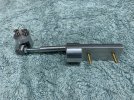
    All the items finished now ready for assembly.
    IMG_1485.jpeg


    IMG_1486.jpeg


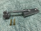
    This is how it all goes together.
    IMG_1487.jpeg


    IMG_1490.jpeg
     
    ENAMEL NUMBER PLATES
  • David Waite

    Western Thunderer
    I know this doesn't look like track work being built but I have a excuse,
    Each year at the start of summer I put two sheets of sarking between the Venetian blind and the glass on each of the four Velux attic windows
    to help stop the Aussie heat from melting everything inside, naturally the windows are on a angle and to put up the sarking is quite a effort so its staying there until summer is over, so the problem is I need natural light I just cannot see clearly enough by the Fluorescent lights to do any track work in the attic so I've been in the shed finishing off jobs to clear the floor space so I can un bolt the lift up sections and take them down into the shed to do the track work well that's the plan.

    What am I up to, well the six Sykes Signal Arm Repeaters need identifying enamel number plates to show which signal they are repeating
    so I made a template out of paper as close to the original shape that was used and to a scale that matches the repeaters I made.

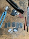
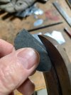
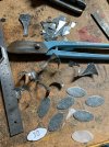
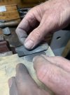
    Out of various odd shaped scrap pieces of galvanised iron I cut out pieces that were large enough to cut out the oval shapes.
    IMG_9567.jpeg


    I cut out one and then used it to scribe the rest.
    IMG_9570.jpeg


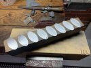
    I cut out a total of eight.
    IMG_9572.jpeg


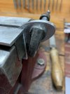
    All clamped together and filed as one.
    IMG_9600.jpeg


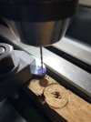
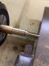
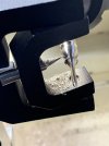
    The hole being drilled will suit some small brass wood screws I have.
    IMG_9606.jpeg


    Each one was sanded smooth.
    IMG_9616.jpeg


    Two more than I need but will be used for future projects I have in mind.
    IMG_9619.jpeg
     
    TYERS , SIGNAL ARM REPEATER INSTRUMENTS
  • David Waite

    Western Thunderer
    My modelling has come to a abrupt halt my good wife wants me to finish the front fence so I am in the process of painting pickets lots and lots of them and once they are all done I have to put them on so I have no time to put aside for my modelling interests therefore I thought I will start the story of my TYERS instruments that I have mentioned from time to time.

    Positioned on the two timber shelves that I made directly above the RE THOMPSON repeater [ see post 166 ] there will be two TYERS signal arm repeaters these will be made to full size.
    After scaling up many photos that I collected I drew a scale plan on paper that I used as my blue print.
    First I made the two Finials there seems to be many different shapes of these on the various instruments made over time so I chose the shape I liked the best.
    IMG_1881.jpeg


    Turning the Sphere.
    IMG_1882.jpeg


    IMG_1884.jpeg


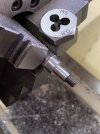
    Turning a spigot before parting off.
    IMG_1888.jpeg


    IMG_1893.jpeg


    Both finished and resting on the full size plan most of the measurements are on other pieces of paper accompanied by some small drawings.
    IMG_1899.jpeg


    Next to be made were the two brass signal posts, the only brass I had happened to be round so it needed to be made square.
    IMG_1912.jpeg


    IMG_1916.jpeg
     
    GWR TRACK CIRCUIT INDICATOR MADE BY WALTERS ELECTRIC MFG Co LONDON
  • David Waite

    Western Thunderer
    Well the latest news is I cannot do much at the moment and probably not for some time as my right arm is now in a sling due to
    damage done to the muscle from over use, which was caused by painting all those pickets and there are still lots to go, and my left arm is also very sore but hasn't got to the stage that the right arm is at which has excruciating pain if I try to move it, so I need to take it easy as I don't want both arms out of action. So what dos'e one do? well we just look for what we can do and my brain is still working at this point and I can push the computer buttons with my left hand so that's something.
    I have mentioned before there are a couple of instruments I would still like to make one is a SR SYKES track circuit indicator similar to the ones I have already made the other is a brass cased GWR RE THOMPSON track circuit indicator made to a diameter of 76mm and mounted on its original type of cast metal stand complete with the indicator plate mounted on the top of the instrument.
    So today I thought I would make a start on the GWR instrument for something to do so I gathered up all my drawing equipment and started looking through the various photos I have so I can draw a scale plan to work from for when I get better, and I can say I have done well today even though I have rubbed out every line and shape many times over trying to get the proportions and sizes to look correct I'm not expecting to get it perfect but if I can at least get it looking as it should that's more than I could ask for, when I get something worth posting on this I will show you.

    Meanwhile here is the story of the GWR Instrument I have made it is still waiting for its timber casing to be made sitting in a box alongside the two TYERS Instruments.
    This Track Circuit Instrument is being made to full size and will eventually sit in the space between two of the Block Instruments on the shelf at Pine Oak Junction. These instruments were made by WALTERS ELECTRIC MFG Co of LONDON for the GWR the timber casing seems to be a standard design and were used for different instruments over time with slight modifications where needed.


    First to be made was the Signal arm unlike the TYERS signal arm the signal arm on this instrument is Balanced with the weights attached to the arm itself.
    IMG_2144.jpeg


    The exact size I required for the two weights were machined out of solid brass stock.
    IMG_2177.jpeg


    The two weights were cut and soft soldered into place and filed to match the shape of the Arm.
    IMG_2179.jpeg


    IMG_2181.jpeg


    The excess solder was machined off to give a nice square edge along the sides of the weights.
    IMG_2187.jpeg
     
    NEW Build / GWR Track Circuit Indicator
  • David Waite

    Western Thunderer
    My arm is on the improve however it soon gets sore if I do a little too much and as I can work the lathe and mill basically one handed I have now made a start on my latest Instrument.
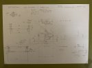
    So as promised here is the drawing that I have come up with, I originally drew a drawing almost the same as this one but with no measurements, every item that is on this type of instrument that I could find in photos were drawn in concentrating on getting their individual proportions correct and with each other which is a challenge when photos are taken from all sorts of angles.
    The Brass casing diameter is the deciding factor for giving me all the measurements.
    I was able to purchase a piece of 76.2 mm OD with a wall thickness of 3.18 mm Brass Tube, so now having a 76mm casing diameter that I could work from I could now scale up a drawing seen below, the measurements are as close as I could get some however will no doubt be wrong but I can alter them as I do the build.

    IMG_2432.jpeg


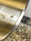
    I skimmed off 0.2 mm from the OD to remove the gouge marks that were left on the surface from manufacturing.
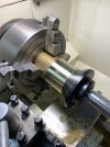
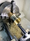
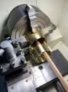
    I used a 4 jaw chuck for better gripping as less force is needed than a 3 jaw chuck and there is also less distortion to the job,
    and to eliminate chatter I used a Pipe Centre.
    IMG_2304.jpeg


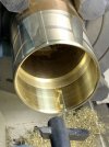
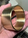
    The front edge radius was turned then the tube was bored out to give a wall thickness of 1 mm and a flat square edge machined
    inside behind the front radius for the glass to rest upon.
    IMG_2309.jpeg


    IMG_2312.jpeg


    IMG_2311.jpeg


    One measurement I could not settle on was the depth of the brass casing so I emailed a heritage railway in the UK after
    finding a instrument like the one I am making in a photo of their museum the following day a email was returned with the
    the measurements I asked for, what surprised me was the diameter of the prototype at 123mm in diameter I had no idea
    they were so large my instrument being at 76mm which is about 1.6 ratio.
    So with the measurement at hand I was able to part this off which I did a couple of hours ago.
    IMG_2425.jpeg


    IMG_2426.jpeg


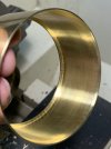
    The inner edge of the front radius which the glass will rest upon can be seen in this photo.
    IMG_2427.jpeg
     
    Top