A Layout Called CHIMTONSTOKE

David Waite

Western Thunderer
David this is fab. Do you possibly design folding roofs for cars for a living? :)
Hi Richard Thanks,
Sorry no I don’t but it is odd you have mentioned that as my cousin has a American 64 Ford convertible that we are about to put a complete new roof covering including the rear window on it, he just had one done by a so called professional but they ruined it and gave him his money back so this time we will have a go ourselves Neither of us would have the conference at our age to do it alone but together I recon we will win.
David.
 

David Waite

Western Thunderer
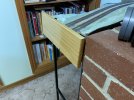
As can be seen the rail ends are protected well
IMG_8744.jpeg


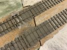
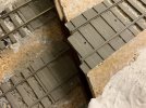
The rail joins are on a greater angle on this Single Lift up Section than the Double Lift up Section and I would not have been able to camouflage
a straight diagonal cut so I stepped the cut instead even with no ballast it doesn't show badly at first glance. There is no side way movement of the joining rails only a increase or decrease of the rail end gap which is controlled by the locating steel dowels in their slots.
Just a note on my track work all my track that I have made so far was built around 1996 I used a Rubber based Tile Adhesive to glue the track work to the base board as can be seen in these photos the rubber lumps look a bit like Ballast it is still solid after all these years. The Adhesive is a powder and you just add water and mix it up it has a long working time once mixed and dries over night. it was good for the super elevation angle of the rails which I set for 50 mph running as it can be built up or levelled out where needed and it adheres almost anything, as can be seen the large area of the milled copper clad sleeper ends are stuck solid the small nails were only there to keep them in place while the adhesive set,
I must remove the remaining nails!

IMG_8732.jpeg


IMG_8735.jpeg


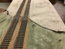
The Left hand Side of the Lift up Section will have a plaster cover over the Locating dowel pin as I have done on the Right hand side
IMG_8737.jpeg
 

michael080

Western Thunderer
David,
I have never seen the use of massive wood boards before.
I have always been using plywood to avoid warping. May I ask what is the secret behind your technique? :confused:
 

David Waite

Western Thunderer
David,
I have never seen the use of massive wood boards before.
I have always been using plywood to avoid warping. May I ask what is the secret behind your technique? :confused:
Hi michl080
I don‘t really have a secret other than using 90x18 Dar pine around the perimeter of the base boards because of its strength it is extremely stiff and it finishes off very nice with a coat of polyurethane however I do have support legs around 1200mm apart which helps to keep it all straight and true , the timber sections under the base board that bind the two sides together are of the same timber but were trimmed down by the thickness of the base board top which is around 18 mm thick some tops are 16 mm thick the sides are rebated also for the base board top to sit in, all glued and screwed together with 50 mm chipboard screws the only reason for the use of the 18 mm thick tops was because I had it given to me and as it is a fixed layout I wasn’t concerned about the weight which is very heavy.
David.
 
Sykes Brass SR Signal Arm Repeater Instruments

David Waite

Western Thunderer
There will be some Signals that will be out of view from the PINE OAK JUNCTION Signal Box so these signals will need to be repeated by Signal Arm Repeater Instruments on the Block Shelf, there will also be some Signals that won't exist such as Distant & Outer Home Signals as my layout would need to be huge to accommodate them however these will be represented by Signal Arm Repeater Instruments. The Lever Frame and Interlocking for these Signals will be in fully working order but instead of operating a Signal which of course won't exist it will work a Repeater Instrument which would be required in any case being completely out of view from the Box.
I require 9 Signal Arm Repeater Instruments in total the first 6 of these I have modelled to represent the Sykes SR brass type of Repeaters these are slightly over half size at 65mm or 2 9/16" in diameter the prototype ones being about 4 1/4" in diameter I believe.
There were a few things that governed the final size of the repeaters first being the space I had to mount these Repeaters on second being the internal size of the mechanism that operated them and third being the casing infact this is what finally gave me the deciding factor.
Having never seen a real one other than in photos I drew up a sketch of sizes and proportions that I worked out from the many photographs I collected and then built them from my minds eye as I went along, it took me 4 months to build all 6 of them and install them in their final position under the Block Instruments.
I will explain how I built them as I post the photos of their construction.


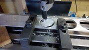
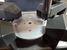
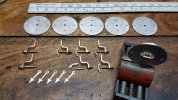
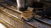
I cut the 6 Face discs out of 5mm Aluminium with the boring head the reason for the use of Aluminium is because its non magnetic.
20200829_162845.jpg


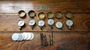
The size of the Repeaters / discs were finally governed by the casing size I had old Oxy & Acetylene gauges from my working past that I realised their casings would suit the purpose well so these were quickly pulled apart, in the photo are old tap spindles these became the source of brass for the bridge bearings
20200830_130612 (1).jpg


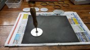
The discs were put into the Lathe centre drilled and the outside diameter finished off then the scratches on the face of each disc were sanded off as shown in the photo the sanding was done a couple of times throughout the build.
20200903_161257.jpg

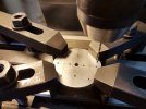
The holes are accurate the lines are not they are just there to keep me in check, my eyes are failing faster than I would like these days so I purchased a DRO for my mill drill as I find it hard to read the rotating scales, not only that the metric scales all read different and I tend to get confused easily these days so the DRO has made a world of difference I can now see the numbers on a digital readout so me and my mill drill has a new lease of life.
20200921_111308 (1).jpg


Counter sinking for the screw heads
20200921_121411 (1).jpg
 

David Waite

Western Thunderer
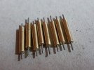
The 6 Bridge Bearings were machined out of old brass tap spindles.
20200831_115909 (1).jpg


The Spindles for the main shaft are 0.95 mm diameter spring wire, this was sourced from my jar of many springs that I have collected over the years I had just enough straight spring hooks from various springs of the required diameter to cut off 12 pieces about 6 mm long.
The drill is 0.95 mm diameter.
20200831_170010 (1).jpg


The 6 finished Bridge Bearings.
The brass screws I used for the mounting of the Bridge Bearings to the Face plate were from the 6 old pressure gauges that I pulled apart, the shape of the screw heads looked better than what is available to buy these days so I decided to use them however the threads on these screws are not standard these are a 3 gauge UNC screw, as the thread is being tapped into the soft Aluminium Face plate I made a tap from a steel screw I found that had the same OD and similar thread pitch I have done this many times throughout my life it works well for cleaning out threads or making threads in soft material like aluminium.
20200831_185156 (1).jpg


These 8 brass 3mm diameter shafts are just waiting to have their pivoting spindles silver soldered in place, once done the spring wire pivots were cut to the correct length and filed up smooth and true each one having a nice rounded end. The two extra main shafts are for another two repeater instruments of a different type but with the same mechanism.
20200926_145953.jpg


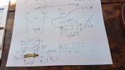
This Plan shows the Level of my Intelligence,
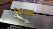
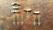
It also shows the first Needle being made when the needle was shaped to my liking I used this as a template to scribe the other 5 needles.
20200902_115129 (1).jpg
Some of the sections drawn on this "high quality" plan of a particular area have two measurements there is a reason for this, because I'm making these from photos the larger of the two measurements is what I trimmed down to first on the first one being made and if it looked good I left it but if it looked to large I would cut it down to the smaller measurement of the two, once the first one was all done it became the template for others to follow.
 

David Waite

Western Thunderer
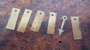
The first Needle became the template for the other 5.
20200902_150005.jpg


Ready for another trimming and filling session.
20200902_150859 (1).jpg


All 6 done.
20200903_142433 (1).jpg


This photo shows the brass Bracket that is mounted to the rear of the face plate, to adjust the end float of the main shaft this bracket is tapped to take a 3/16 BSW brass screw which becomes the adjustable rear main bearing with locknut this supports the rear of the main shaft it is drilled with a 0.95 mm drill same as the front Bridge bearing
20200926_171643.jpg
 

James Spooner

Western Thunderer
David,
I have just caught up with this thread and, as others have said before, ’wow’ just doesn’t do this justice! The thinking that is behind all of the designs and then the sheer skill and craftsmanship that have gone into creating them, frankly just take my breath away. Many thanks for sharing this with us and I will be a regular visitor to this thread in future.
cheers
Nigel
 

David Waite

Western Thunderer
David,
I have just caught up with this thread and, as others have said before, ’wow’ just doesn’t do this justice! The thinking that is behind all of the designs and then the sheer skill and craftsmanship that have gone into creating them, frankly just take my breath away. Many thanks for sharing this with us and I will be a regular visitor to this thread in future.
cheers
Nigel
Hi Nigel
Thank you for your kind words I appreciate it very much, it is a pleasure to share my efforts with WT . As a new member to this group I am slowly catching up with the vast array of modelling that the other members are also sharing, of which they have produced or are producing, I am constantly astounded with the workmanship the likes of which I have never seen before.
David.
 

David Waite

Western Thunderer
A rear view showing the Brass bracket in position and the Brass screw which is the Adjustable rear bearing along with its locknut.
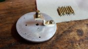
20200926_150445 (1).jpg


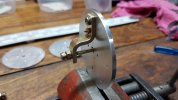
Showing the main shaft in position.
In this photo there is a Armature still to be attached to the main shaft, the weight of this armature plus the weight of the Needle which isn't much will make them both hang downwards "by gravity" this is the Fail Safe position and the Needle will point Downwards to the word WRONG on the face of the Instrument.
20200926_171703.jpg

I will jump the process a little bit so I can explain about the relays as these became the source of the Armatures.
Originally I was going to build a small Galvanometer to operate each Instrument similar to Spagnoletti's design but I soon dismissed this idea as the cost of the copper enamel wire had a ridiculous price tag. After having a good think about how I could make these work I figured I could operate these Instruments by individual coils which would make the Instrument work exactly as the prototype dose but by a different method.
As individual coils cannot be bought off the shelf I realised Relays would be a source of supply that had coils with the correct resistance and good Magnetic pull so I started experimenting with old relays of various types I had.
I attached a Thermocouple to each coil and monitored its Temperature at different voltages, I then pulled the Armature off each relay and checked this again on average the temperature rose up by about 10C some worse than others while I did this I also took note of how much Magnetic pull each coil could give at a particular voltage, at the end the Relays that I have been using for the Turntable and Lift Up Section proved to be the best for what I required.
The end result when these Instruments were finished was good the Pick up voltage is around 6 volts DC but is sluggish at 8 volts they move quickly the coil running temperature is around 39C at 8 volts and 47C at 10 volts so I had a win.

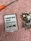
This is the type of Relay that I used.
IMG_2388.jpeg


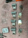
The first thing I did was to remove the Armature with its contact piece.
IMG_2389.jpeg


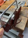
Next I cut off the lower contact section.
IMG_2393.jpeg


The section with the coil terminals that remained attached was tidied up with a file.
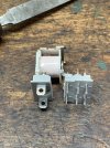
IMG_2396.jpeg

The left hand section of the piece that is being cut off in the photo is to become a Armature for one of the Main shafts.
The metal on this relay is of Soft Iron so it doesn't become magnetised when held against a electro magnet for any length of time.
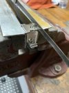
IMG_2400.jpeg


The ruff sawn metal remaining on the coil including the spring mount was filed down level with the plastic bobbin
The reason for this is this side of the plastic bobbin rests against the rear of the Aluminium Face plate and in doing
this the coil only requires one mounting screw to hold it in place.
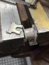
IMG_2401.jpeg
 

David Waite

Western Thunderer
What are to become the Armatures have been cut off and trued up with a file removing the least amount of material as possible.
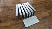
IMG_2422.jpeg


One end of the Armature was milled to leave a small square piece protruding about 1.75 mm this becomes a locating dowel.
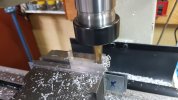
20200927_140922 (1).jpg


A small hole was drilled into the side of the main shaft this is what the locating dowel of the Armature is pushed into it positions the
Armature correctly in relation to the centreline of the coils it also holds the two pieces together when they were silver soldered.
20200927_104934.jpg


The main shaft finished
The end of the main shaft closest to the top of this photo with the grip marks on it is the end that the Needle will be soldered to.
20200927_170221.jpg
 

David Waite

Western Thunderer
Next the Coil Brackets.
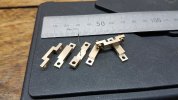
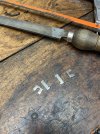
Due to the restricted space within the casing the Brackets that hold the Coils to the rear of the Face Plate were made from flat pieces of thick Aluminium, each plate gives Two brackets, the extra Two pieces are for the Two Tyres Instruments yet to be built.

20200930_151137 (1).jpg


Two Brackets Milled as One.
20200930_162329.jpg


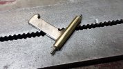
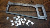
Finished shape to be cut in half.
20201004_133105 (1).jpg


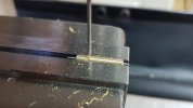
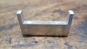
Allowing plenty for the hacksaw cut the Brackets were then Milled to their correct length.
20201004_133251 (1).jpg


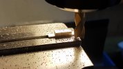
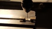
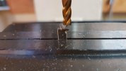
Two mounting holes were drilled in the base of each Bracket one clearance hole through the thin extension for a screw to fix the Bracket from the rear of the Face Plate the other blind hole being tapped 8BA in the photo is for one of the counter sunk 8BA screws that are on the front of the Face Plate that pass through the Face plate to hold the bracket in position.
20201007_154332_001 (1).jpg


The shallow recess that was formed by a milling cutter that can be seen was done to allow the squashed [ riveted ] end that was formed on the Iron centre of the coil to sit into, the clearance hole being drilled is for the coil attaching screw.
20201008_130201 (1).jpg


Without damaging the windings of the coil a 2.5mm tapping drill was run through.
20201008_151631 (1).jpg


Tapped just enough to do the job.
20201008_152523.jpg


Coil and bracket screwed together.
I didn't have a photo of the Sykes Coil and Bracket so I used this one which is from one of the Tyre's
Instruments these have their Coil Brackets attached from the rear of their Face Plate only there being no tapped 8BA
threaded hole in the Bracket hence the two clearance holes that can be seen other than that they are identical.
IMG_2418.jpeg
 

David Waite

Western Thunderer
The last items to be made for the mechanisum are the two Needle Stops for each Instrument the prototype ones being screwed into the face plate. Due to their small size I wasn't going to run or tap threads with these so I turned these out of brass but with plain shanks that have a slight interference fit in their holes, they are slightly longer than needed protruding out the rear of the face plate about 1mm so where I could put a small drop of epoxy glue for peace of mind. My Engine Lathe is a bit big for my modelling so I use the chuck and part of a old armature shaft from a burnt out Dremel tool this holds and works well on soft brass.
20200913_154926 (1).jpg


I used a razor saw to cut the trick screwdriver slots.
20200913_164011 (1).jpg


I never lost any I managed to find the ones I dropped.
One of the items I have in my workshop are rubber floor mats to stop the creeping cold from rising up my legs from the cold concrete floor they are covered in molded holes so when I drop something 9 times out of ten I lift the mat and with a torch scanning across the surface I find the one that tried to get away some things do and they remain a mystery.


20200913_164500 (1).jpg


One of twelve finished
20200913_174409.jpg


A little jig I made to cut the plastic buffers all to the same length these slide on the brass Needle stop 'imitation screws / pins' what ever you wish to call them.
On the prototype the Needles rest against these Buffers but on my Instruments the Needles clear these Buffers by 0.5mm this is to prevent damage to the Needles, the Needles stop in a exact position when the Armature rests against the Iron core of the coil.
20201005_120614 (1).jpg
 

David Waite

Western Thunderer
At this point of the build I stripped all the items that were attached to the Face Plates which were fitted as a trial fit up as I went along, the odd scratches were removed and then they were cleaned and a etch primer was applied.
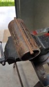
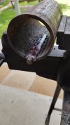
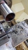
Next to be made were the 6 Spacer Rings that seperate the Face Plate of each Instrument from the rear of their glass pane, I decided to use a off cut of Ammonia pipe which I have had stored for almost 40 years doing nothing, so much for the severn year rule! anyhow Ammonia pipe is seamless and thick walled so its exactly what I required but the piece I have is a little small on the OD size for what I needed but if the circumference was increased by 13mm the pipe would then have enough material in all its dimensions to enable me to machine out of it the sizes I required to produce the 6 Spacer Rings, the next photos show how I did this.


A piece long enough to do the job was cut off.
20201009_132700.jpg


A cut was run down on one side only.
20201009_133154 (1).jpg


This cut was opened out and a piece of solid 13mm rod was fitted in the gap.
20201009_142140.jpg


The solid rod was welded by Ark into position with just GP rods but with good penetration so to eliminate any cavities.
20201009_143910 (1).jpg


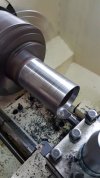
The end was faced off and the OD turned to the required size this didn't require a good finish as it isn't seen.
The inner Diameter has a taper of 5 degrees starting at 0.75 mm at the thickness of the front edge closing the Spacer Rings ID to a slightly smaller diameter at the rear.
20201009_161000.jpg


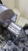
Parting off the required length.
20201009_184235 (1).jpg


The first one off the production line, the thin front edge is facing up.
20201009_162540 (1).jpg


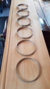
All six done these were cleaned up and sprayed with a etch primer then a coat of Aluminium/Silver top coat was applied
they were then put aside ready for their final assembly when required.
In this view the Rings are face down showing the extra thickness of their rear edge [smaller ID].
20201010_095841.jpg
 

David Waite

Western Thunderer
Next job to be done was the alteration of the six Oxy & Acetylene Brass Pressure gauge casings.
The casings were just a little short in their depth for what I required so I removed the rear of the casing to allow the mechanism to pass through and into their timber mounting board.
20201027_185323 (1).jpg


The Brass casings are made of a two pieces that fit together with a very tight interference fit, only the rear section is shown in the photo.
20201027_185555 (1).jpg


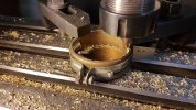
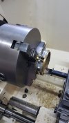
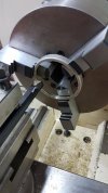
Finishing off the new rear opening in the Lathe.
20201027_191543 (1).jpg


The mechanism is a slide fit into the Brass casing.
20201027_192204 (1).jpg


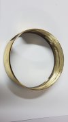
The front half of the Brass casing is shown here and as you can see the rolled edge is rather large and baulky looking
I thinned this down including a smaller new radius on its outer inner diameter to make it look more refined at the same time keeping a right angled inner edge against the glass, this was a time consuming job, only a very little pressure could be put on this front section of the casing with the jaws of the chuck so to prevent its distortion, there for very light cuts were required to prevent the brass section from spinning in the chuck or worse.
After all this was done I assembled all the two halves and polished off the original Nickel plating with the emery wheel then polished the casings to a bright bass shine on the rag mop.
20200908_162939.jpg
 
Top