A Layout Called CHIMTONSTOKE

David Waite

Western Thunderer
Hello I’m David Waite
First of all as the title says the layout is called CHIMTONSTOKE, as I explained to the group in my introduction as a new member
I built the house myself and naturally as a railway enthusiast I wanted a Train Room so I structurally designed the house to support an Attic. The Attic room measures 30’x 12’ there is a chimney and a staircase in the room that the layout had to get past and Four windows that need unhindered access and of course there’s the walking areas to access the various sections of the layout.
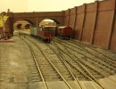
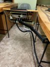
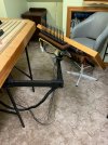
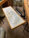
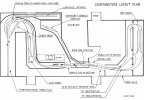
I’ve attached a floor plan I drew today outlining the Attic & layout which should explain what the layout is about better than I could explain in words, the plan is not to scale and is far from accurate but it shows the basic track configuration. As can be seen CHIMTONSTOKE is a Terminus station with a double track mainline that splits at PINE OAK JUNCTION via the double track junction, the Main Line heads towards COALCHESTER and the Main Branch to BRIDGETON both these destinations are return loops and will each have 4 storage sidings on them, the BRIDGETON loop will be on a higher level and directly above the COALCHESTER loop and these will be in the storage room outside the end of the Attic room. The track is built to OO gauge but with tight tolerances using FB / NS code 70 rail on copper clad sleepers so far I’ve built about 20‘ of double track main line and some of the WAITECOTT branch. There are 3 lift up sections, one small manual lift up section near the chimney and a double lift up section on the down side of PINE OAK JUNCTION, this double lift up section has a manual side which is lowered down first then the other half is lowered and raised by a 12 VDC geared motor which gets its power supply from a SLA battery that is charged by a solar panel out on the roof of the house the reason it is battery powered is because we often have power outages and the reason I made the section electrically driven is because my shoulders are not good so the motor lifts it for me and why is it a double lift up section that’s because I have a TV under the window and when both sections are up I can watch my Television . There is no scenery and basically empty base boards but intend to change that situation next year.
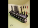
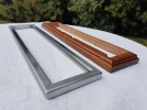
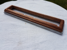
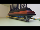
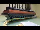
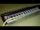
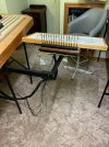
The Layout will be worked by 6 hand built SINGLE WIRE TWO POSITION DOUBLE LINE BLOCK INSTRUMENTS all of which were installed in 1996 and are in full working order. PINE OAK JUNCTION has a 30 Lever All Steel Lever Frame and will be fully mechanically interlocked, signals that are out of sight from the Box or signals that won’t exist due to scale distances will be repeated by Signal Arm Repeater Instruments, 6 have been made and 3 are still in production only their timber casings need to be made, I will show photos and give details of all the items I’ve made so far when I learn how to operate my new computer over the coming weeks this is where my daughter put all my photos.433F7813-0ACF-4A8D-936A-E738C603C959.jpeg
 
LEVER FRAMES

David Waite

Western Thunderer
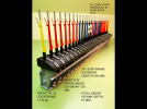
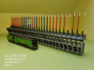
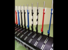
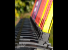
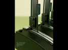
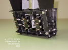
I will start with a description of the 3 All Steel Lever Frames that I built in much of my spare time over 3 years and finally finished them in 2019. They are of no particular prototype but a combination of many, a sketch was drawn up to give good proportions and sizes inc radius, tapers ect other than that they were just built through my minds eye as I went along. The smallest is a 3 Lever Frame for the control of points at WAITECOTT branch station, the next is a 15 Lever Frame, levers 1 to 14 will control the points at the loco depot and lever 15 will control the Locking on the Turntable. The largest frame is a 30 Lever Frame this will control all point work and all running signals including two Detonator placers at PINE OAK JUNCTION this frame will be fully mechanically interlocked.
All the components were made by hand and machine or combination of both, various grades of steel including Stainless steel were used, the only non steel item used and the only item I didn’t make other than screws, nuts , springs & pins ect were the etched brass Lever number plates that I purchased from DCC Concepts. Many jigs were produced as required to hold the various pieces when being made to give a uniform build quality and positioning .
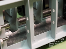
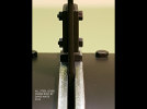
The Lever Handles are 304#SS turned & slotted and then 45%silver soldered to their Mild Steel (MS) Lever the Catch Handles are 410#SS (high tensile) and are 45%silver soldered to their MS-U bracket. The Quadrant sections are Bright MS milled, I then made a die and pressed them into shape at 4000 psi each to give them all a uniform shape including the spring back these were then Blue Zink plated “by others“ to prevent the bare metal guides that the catch block slides along from rusting.
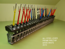
The main shaft is 5mm dia 304#SS, each lever has a bush 45%silver soldered into a extension piece that is spot welded to the bottom of its lever there are two floating bushes between each lever on the shaft to eliminate any friction the total end play of all levers inc bushes after assembly on the 30 lever frame is .005” this gives a perfect centre position of each lever between its two adjacent quadrant sections. The Clevis pins on the catch handle are tempered pins and are 0.9 mm dia the catch rod is plain mig wire flattened and drilled at the end to suit the pins the catch block is attached to this rod by 45%silver, this rod assembly was then pickled and copper coated to prevent rusting from the flux, the spring block that is attached to the lever is only acting as a guide as the spring assembly is below the quadrant as you will see in the photos, I think I’ve covered the main sections which wouldn’t have been known unless told hopefully the photos will load, if all goes well I will add to them over the next few days.
AFAF3E37-E963-4705-B17F-DB0376460C1D.png
DCF596B3-EB95-45AF-AE4F-5DCA226C11F6.png1D0AFBEE-C08B-4C4B-8EC4-162505AC2975.pngEEFF8CF9-D960-4398-9C13-EFD58C680A94.pngA9B6E637-9102-4F84-9032-4694033DFDB1.png361DE630-7D06-4209-802F-782A373B615A.png77E1D5AB-4F56-4321-A635-43C96DFC40FE.png14236CAC-FCD0-4EEE-9B74-DA7968F7743C.png23554F73-764F-4DF1-A9A2-E4964A49B830.png9AD7CC71-DA4F-4705-A1D2-74AE88A5FC84.png4AC1959A-CDE7-4E60-8CA9-D95BD2318551.png5206FE9D-3077-4203-9DFD-4C7D42F28F97.pngC5B502A2-1643-477E-969D-55352C0C0EE6.png94B83F9F-E3DD-472A-A300-69B0772A050D.pngADB04E0F-CF14-4D2A-A83A-AC7A2D6D7A5A.png318D65A5-0E64-4426-942F-3E418D5A3F5C.png
 

David Waite

Western Thunderer
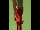
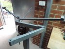
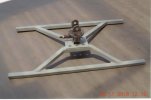
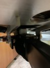
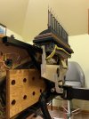
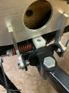
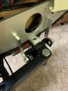
Continuing on from the last photo which is of the 15 Lever Frame, this frame is mounted on the top edge of the Loco Yard Control Panel, as I will need to control the loco yard from various sitting or standing positions I needed the panel to move so I can have it near me where ever I am within the area. To do this I built a two piece articulated Arm that is mounted on the layout support leg directly in front of the loco yard, the arm is made of steel and is pivoted on ball races at each joint. At the control panel end there is a tilting head piece with two pivoting movements, first it can tilt the panel side to side to enable slight levelling of the panel, second is the ability to tilt the panel from a level to upright position and hold it at any chosen position, it holds its position by friction which is maintained by a adjustable heavy spring that is under compression. As the panel angle can be in any position anywhere from a level position to the upright position the Lever Frame needed to sit into its own steel frame that is attached by a hinge along to the top edge of the control panel Support frame. The ends of Two Aluminium arms are connected to this steel frame the other ends are connected to the Tilting Head piece this enables the Lever Frame to keep a horizontal position no matter what angle the panel is at .
7472CED0-084F-4927-924B-1BDB91A916E1.png7111BD53-9421-44E1-A5F2-A1F1C040DFBF.pngAB8838AC-DE8C-467A-9219-B277167585E4.png8FC7B097-8A94-4159-8E9F-2C78775FD9DB.png8FC051BD-AD40-4180-BEE5-B909E706B59E.png138CA960-C349-407B-8D7C-707D5155B3F4.png
 
David

I have just caught up with this - wow! The lever frame is just superb, well done. It put me in my mind of a group who used to display lever frames at the AMRA exhibition in Sydney - probably 10 years ago now. These guys built the frames to about 1 in 6 scale - were you part of this group?

I liked your track plan and was pleased to read that you have tightened up the tolerances and use hand built track. I have done something similar in 7mm and it works very well. Based on the Merchant Navy in one of the photos am I right in thinking this is an SR based layout?

Regards

G
 

David Waite

Western Thunderer
Hi Graeme
No I wasn’t part of that group but I would love to see what they had made.
As a 00 modeller I’ve never been happy with the way locos and rolling stock drop and bounce through point work
and with a variety of different wheel profiles and wheel gauges that I have I decided to experiment. First was by using Code 70 FB rail this gives in my eyes a better definition of distance and tends to hide the fact that 00 gauge is a narrow gauge and by soldering it to copper clad sleepers this enables wheels with larger flanges to run which just clear the sleeper tops as for not having chairs ect, being use to seeing Aussie track that always used dog spikes and from a distance one could never see the spikes anyhow only the plain rail as the spikes are so small so to me it looks good.
l experimented with various gauges to set flange way clearances and eventually found a clearance that all locos and stock would run through smoothly from Wrenn to fine flange Athern locos from a slow speed to high speed through the point work.
Ah the Merchant Navy!
I will explain, Starting from the age of 16 as a apprentice to a Industrial mechanical industry I’ve always had a keen interest in anything mechanical especially things of the past, many of the machines I worked on were from a bygone era which all had unique or not so unique designs. I would often be given new jobs from one particular engineer who never did anything by the book in fact I really think he was from another planet, anyway he had guts he designed and tried things that nobody else would ever dare do and I often wondered where he ever got his ideas from, anyhow naturally I would have to get things going whether they ended up working to 100% design or struggled to do the job or constantly needed attention to keep things going crossing my fingers as I shut the plant room door, I just like things different it was a challenge.
This is why I admire the different mechanical designs of all the four companies including the locos from 1800s and the BR period all being different in some way some good and some not so good and especially those engineers who stepped out side the square into a design of not normal such as Bullied so that’s the reason behind the Merchant Navy and a interest in the SR and of course GWR / LMS & LNER so you see I’m everyones friend. So no it’s not a SR solely based layout
Regards David
 

jonte

Western Thunderer
May I ask, David, the flangeway clearance you settled on eventually? I made some HO track for an American based layout some years ago using car feeler gauges to set clearances, but can’t remember for the life of me the measurement.

Tried all sorts over the years, even OO SF, which was hit n miss, as it’s dependent on the factory setting the correct BTBs.

Many thanks.

jonte
 
David

Sadly I don't have the details of the guys with the lever frames, but if I ever see them again I will let you know. Personally I use Modratec frames which, whilst very "functional" in appearance, suit my needs admirably.

There is a long standing BRMA member in Sydney who has done a lot of work on track and wheel standards. What he found was that many model standards are full of nominal dimensions that don't properly relate to one another and do not have workable tolerances. I have latched onto this work and developed my own spreadsheets to set my own track and wheel standards - I will send you a copy off line - you may find it of interest. I build my track and modify the wheels to make sure they are compatible. I think that is the key - you don't have to use exact scale wheels and track - they just need to be compatible. However, there is no doubt that as you tighten up flangeways you will eliminate wheel drop and running through obtuse (K) crossings will become a lot more reliable. Personally I think it also looks better.

The photo below illustrates some of my track - this is 32mm gauge track with reduced flangeways. It isn't as nice as Scale 7 but I think it looks ok. (I need to finish off chairing the crossings). More important to me is that it works close to 100% reliably.
Cheapside throat.JPG

Thanks for the info about your interests. I think Bulleid was one of the great locomotive engineers although no doubt the SR management possibly thought otherwise at times. As an engineer myself I always thought that you could have a highly innovative solution or a risk free solution - having both is a bit tricky, especially on a limited budget.

Regards

G
 

David Waite

Western Thunderer
May I ask, David, the flangeway clearance you settled on eventually? I made some HO track for an American based layout some years ago using car feeler gauges to set clearances, but can’t remember for the life of me the measurement.

Tried all sorts over the years, even OO SF, which was hit n miss, as it’s dependent on the factory setting the correct BTBs.

Many thanks.

jonte
Hi jonte
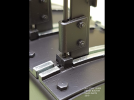
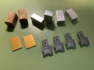
The Flange Way Gauges are 1.5 mm which are the gold coloured pieces of aluminium one narrow end on each is slightly curved the other end is straight, the Aluminium blocks are machined to 16.5 and 25mm long two used (in pairs) for setting the crossing position in relation to the stock rails these can be used length ways or on their end, the wooden gauges are 16.25 again 25mm long I use these to move things a little while soldering to save the fingers and the KADEE three legged track gauges can be flipped over to suit code 100 on one side or code 70 the other, the three legs set the track on curves to a slightly wider gauge I've had these for over 40 odd years
Regards David.

IMG_7979.jpeg
 
MOVABLE CONTROL PANEL

David Waite

Western Thunderer
This next section is about the construction of the movable Loco Yard control panel.
I lost many of my Digital photos at one time but luckly I had some made into prints before this happened so some images are scanned I apologise if they appear a bit grainy.

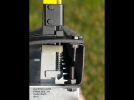
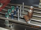
This photo shows the bearings and their housing tubes that will be welded to the ends of the arms.
DSCN4739.JPGThe finished and assembled arms

DSCN4851.JPGThis photo shows the arms fitted to the support frame this frame will be attached to the legs of the Base Board, the free end of the arm is where the Tilting Head piece is attached to. DSCN4853.JPGConstruction of the Tilting Head Piece.

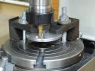
This photo shows one of two identical size discs, this one having a slot the other disc has a hardened pin fitted that rides in this slot this gives a limited amount of twist to enable horizontal levelling of the control panel when needed.DSCN4961.JPG
These discs are compressed together by a spring under compression that is hidden inside the rectangular tube that is attached to the slotted disc in the photo this gives friction to the discs to keep the control panel firm and in place.
Scan 2.jpeg
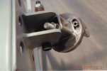
This photo shows the tilting compression spring that gives friction to the control panel as it's moved from vertical to the horizontal position and holds it at any given position.Scan 1.jpeg
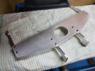
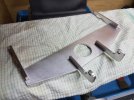
Here is a rear view of the frame that the control panel is mounted to, in this photo there are still two more brackets to be welded to the slotted disc which is the lower disc in this photo, these brackets are what the two aluminium arms are attach to which keep the Lever Frame horizontal at all times. Scan 6.jpeg
 

David Waite

Western Thunderer
The next two photos show the two Aluminium arms that connect the Tilting Head Piece to the steel frame that supports the 15 Lever Frame, (on previous photos of the 15 Lever Frame you can see the connecting brackets on the underside at the ends of the steel frame) because the two arms are connected to this steel frame at the ends and are wider apart than their position on the Tilting Head Piece these arms were cut in half and attached to a shaped piece of Aluminium.20191030_212108 (1).jpg20191030_212050.jpg

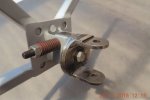
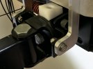
This shows the Aluminium arms attached to the metal brackets on Tilting Head Piece, the Nylon Stop Block is what the Control Panel frame stops against in the horizontal position.
IMG_7926.jpg

Oops I can see I've chipped the paint, don't worry I'll fix that. IMG_7974.jpg

The two metal brackets also act as Limit Stops when the Control Panel is turned exactly parallel to the Arm.IMG_7976.jpg

This view shows the Control Panel in the horizontal position resting against the Nylon Stop Block.IMG_7977.jpg

Rear view, more chips!
IMG_7927.jpg
 
Movable Control Panel

David Waite

Western Thunderer
The completed assembly in the vertical position, there is still a metal cover to be made which will cover and
protect the underside of the switches and wiring on the Lever Frame this cover will also have rubber buffers
attached at the rear of it to protect the edge board on the layout.
IMG_8038.jpeg

In a tilted position. The chrome thumb screw that can be seen holds the Control panel in place the panel
is hinged along the lower edge of its support frame.
IMG_8037.jpeg

The next 3 photos show its movement from vertical to horizontal.
IMG_8057.jpegIMG_8056.jpeg
IMG_8055.jpeg

Facing towards the South.
IMG_8058.jpeg

Facing towards the North

IMG_8063.jpeg


IMG_8064.jpeg

Can be turned on almost any position and angle.
IMG_8068.jpegIMG_8069.jpeg

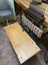
The panel is shown in its lowered position for access, the pink string isn't permanent there will be 2 small
chains when finished, there is also a rear ply cover that will be fitted to the rear of the Panel when finished as
seen in the next photo
IMG_8048.jpegIMG_8042.jpeg

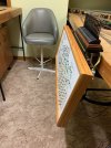
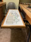
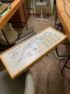
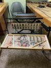
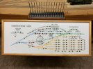
The panel face was made for me in the mid 1990s from a drawing I did. It is a laminated two piece sheet, clear on white Perspex, all the lines and text was milled through the white rear sheet and slightly into the clear face sheet then paint was applied into the recesses its held to a timber backing by all the switch lock nuts across its face.
IMG_8045.jpeg
 

Joe's Garage

Western Thunderer
I think there is something very satisfying in operating a layout with a lever frame, would love to have the room for such.
Very realistic and lovely.
Julian
 
Top