paratom
Western Thunderer
Hi David
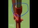
Fantastic work on the lever frame. I am thinking of making one for my layout with a tappet frame. I will do my design in CAD first and feel comfortable making most of the parts appart from the main lever arm. Did you mill this out of round stock using the side of milling cutter to get the flutted shape at the end or did you file the ends to get that shape. I'm thinking that I will have to make a jig to hold the material to do this.
Thomas


")


") )
)


