A Layout Called CHIMTONSTOKE

J_F_S

Western Thunderer
Real craftsmanship as ever David - very well done!

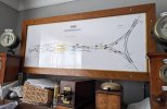
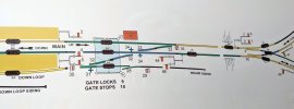
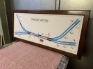
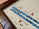
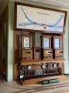
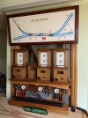
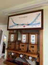
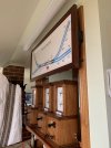
I confess I chose a more basic approach: my paper diagram (1.1m x 0.4m) was done in MS Powerpoint and the frame is made from Keruing, rebated for an Acrylic "glass" and bolted to a ply frame which incorporates the mountings for the LED Track Circuit 'Lamps'. I do NOT suggest using Keruing for this job as it moves far too much in response to climatic conditions (my excuse for the poor mitres!) but I had it in stock ...

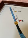
Just off-shot are a load of SYX repeaters; I think Sykes took less care making theirs than you did with yours :)

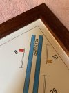
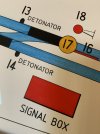
The detail shot shows that unfortunately, the print has faded over the past 13 years - a problem you have avoided by hand-drawing ... a skill to which I could only aspire ...

with best wishes and looking forward to developments...

Ford SB Diag 1.jpgFord Detail.jpg
 

David Waite

Western Thunderer
Real craftsmanship as ever David - very well done!

I confess I chose a more basic approach: my paper diagram (1.1m x 0.4m) was done in MS Powerpoint and the frame is made from Keruing
Thanks Howard
Thats a Marvellous job you have done on your diagram, thanks for sharing,
I will never learn the computer skills to enable me to do what you have accomplished it’s just not me but I certainly enjoy seeing the neatness that a computer can turn out and I admire the skill of the operator.
I have never heard of Keruing before and it seems to go by a lot of other names as well, it’s certainly a tough timber at F11 to F17 un seasoned and F27 seasoned I noticed it contains oleo- resins that leach which can be a problem with paper this is why I have sealed the Merbau with shellac as it can leach, compared to many chemical sealants the PH of natural Shellac is still one of the lowest, slightly alkaline, and is a preferred sealant for sealing timber boxes that contain Archival documents.
You mentioned your print has faded, Fading by UV is certainly a problem, some of the spines on my books have slightly faded I believe it’s down to the fluorescent lighting so not wanting to see my Signal Diagram fade I have used Museum glass which blocks 99% UV at least if it dose fade all I can say is I tried.
David.
 
Last edited:

J_F_S

Western Thunderer
Our previous garage was made using second-hand timber from a private owner wagon ('Bennetts of Swansea') and I was surprised to find when I cut it up that the solebars were Keruing. These days it is most commonly used for lorry flatbeds etc. And that is the best use for it - steer clear: it has many evils! But I have a lot of it, so it gets used for non-critical jobs!

Yes, UV was the problem with my diagram (you can see the reflection from the window) - thanks for the tip on Museum Glass - I had not come across that before. I suspect you will be fine with your digram as the material you used are vastly superior to printing inks! The good news for me is that I can just take the file back to the printers and get a new one (I might even correct the mistakes first!).

Best wishes,
Howard
 

David Waite

Western Thunderer
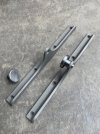
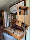
Next items to be made were the two sets of brackets that hold the Frame to the architrave surrounding the window
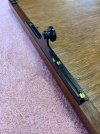
these needed to be made in such away to allow the Signal Box Diagram to be lifted off now and again so I can clean the window behind it, which is a task as the block shelf and Instruments already get in the way of cleaning.

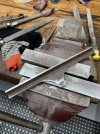
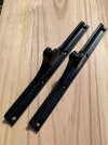
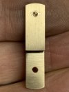
I had a piece of 2" x 2" angle iron which was just long enough to do the job, it was very pitted with rust however this suited me as it will give a old look to the finished item.
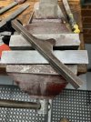
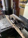
Some milling to square off the straight run edges but mostly cut by hand a filed into shape.
IMG_8545.jpeg


IMG_8547.jpeg


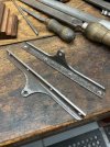
When fully assembled the Signal Box Diagram has a bit of weight to it so making these long brackets will give good support to the timber sides.
IMG_8549 2.jpeg


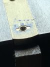
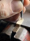
I turned up two top hat pieces which have a small shank that pass through the brackets to act as a rivet.
The two brackets were then sand blasted ready for painting.
IMG_8557.jpeg


The shank was heated with the torch and peened over
IMG_8559.jpeg


A etch primer was applied then a semi gloss top coat to finish off.
IMG_8563.jpeg


IMG_8669.jpeg


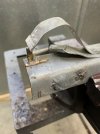
In this photo the wall support bracket is being made
IMG_8560.jpeg


The brackets all fitted up and work well
IMG_8630.jpeg


Almost there.
IMG_8626.jpeg
 

James Spooner

Western Thunderer
Next items to be made were the two sets of brackets that hold the Frame to the architrave surrounding the window
these needed to be made in such away to allow the Signal Box Diagram to be lifted off now and again so I can clean the window behind it, which is a task as the block shelf and Instruments already get in the way of cleaning.

I had a piece of 2" x 2" angle iron which was just long enough to do the job, it was very pitted with rust however this suited me as it will give a old look to the finished item.
Some milling to square off the straight run edges but mostly cut by hand a filed into shape.
View attachment 190721


View attachment 190722


When fully assembled the Signal Box Diagram has a bit of weight to it so making these long brackets will give good support to the timber sides.
View attachment 190723


I turned up two top hat pieces which have a small shank that pass through the brackets to act as a rivet.
The two brackets were then sand blasted ready for painting.
View attachment 190724


The shank was heated with the torch and peened over
View attachment 190725


A etch primer was applied then a semi gloss top coat to finish off.
View attachment 190726


View attachment 190731


In this photo the wall support bracket is being made
View attachment 190727


The brackets all fitted up and work well
View attachment 190728


Almost there.
View attachment 190729
David

That whole ensemble is absolutely stunning with all of the work carried out to a consistently top level of craftsmanship. I am awestruck.

Nigel
 

David Waite

Western Thunderer
The assembly was a little nerve wracking as the Diagram had to be cut in such away as to centralise the margin on the Diagram with equal spacing from the frame and at the same time allowing the matt board to sit on the bottom rail of the frame that the Diagram is hanging from.
The Diagram hangs in the frame and is glued to its backing matt board along its top edge only using a acid free PVA, a acid free masking tape was then placed along the top edge of the Diagram then folded over the back of the supporting matt board as a extra hold.
The glass is a 2.8 mm Non Reflection 99%UV block out "Museum glass" I used this to protect the Diagram.
The matt board spacers between the glass and the Diagram and the matt board that supports the Diagram are both 3.8mm thick and is acid free.
The paper that the Diagram is drawn on is 380 gram acid free cotton paper made by Arches in France.

IMG_8672.jpeg


The glass is very clear
IMG_8674.jpeg


IMG_8695.jpeg


IMG_8699.jpeg


IMG_8696 2.jpeg


IMG_8705.jpeg


In this photo there is a lot of glare coming through from the window but the glass is somehow doing its magic as can be seen
compared to the normal glass on the Block instruments.
IMG_9098.jpeg


IMG_9109.jpeg


When I originally decided to have the Diagram positioned on a angle as many were hung I was concerned
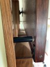
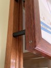
that the cotton paper might bow towards the glass and it did after some time so I made two spacers to set the frame out from the architrave in a vertical position.
IMG_9178.jpeg


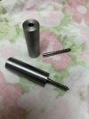
Frame spacers being turned up .
IMG_9538.jpeg


The heads of two wood screws were cut off and their shanks were pushed into the holes on the steel spacers
these were then silver soldered in position they were then painted and a silicone buffer was stuck on the end.
IMG_9540.jpeg


The spacers were hand screwed into pilot holes in the architrave
IMG_9725.jpeg


IMG_9730.jpeg


The bow in the Diagram started to disappear over night by the following day it was gone.
IMG_9731.jpeg


IMG_9733.jpeg
 
Last edited:
A NEW CHALLENGE IN LIFE

David Waite

Western Thunderer
Well this new thread title above says it all,
At the start of this year I up dated my glasses, I had new lenses made complete with new frames but by mid May I could not clean the
misty haze off the new left lens no mater what I used, however it wasn't a grubby lens a trip to a Ophthalmologist confirmed I had lost vision in my left eye, apparently my eye is working as good as the other but the jelly like substance that makes up the eyes inside has failed and cannot be repaired so every thing I see through my left eye now is blurred, But I'm not giving up I have repaired and built things all my working life its what I'm all about, it was once my job that I earn't a living from and now I put my skills to home maintenance and my hobby I'm lost without tools they are my life. So since mid May I kept out of the shed and concentrated on doing day to day things like walking up steps without tripping forward and general maintenance things around the house that didn't require good vision to do and of course learning to accept what has happened this I can say I have done, I have accepted it as one must, WT has been a important link to my hobby its been a struggle to find and post photos but it has been a driving force more than you could imagine.
Two weeks ago when I decided to have ago at making the spacers for the rear of the Diagram Frame was the first time I had gone into the shed to make anything since May, working the lathe was second nature no problem I'm so glad the dials are metric and imperial I was bought up on IMP and they are so much easer to work and see which is important to me now, each IMP division is a thou the metric divisions are .003 / .002 and .015 on the metric scales on the Lathe and Mill so simplicity is the key, I fitted a RDO on the mill sometime ago so I don't have to look at the hand scales anymore other than the down feed, the biggest problem I found was lighting I need to put extra movable lamps on the equipment.
I found I have to get so close to the job now safety has become a concern in fact I had to remove a handle off the mill so I could get my head in closer to see what the cutter was doing with my glasses and magnifier head piece on its about 4" from the cutter to see clearly.
Am I making anything, yes I am so pleased to say, I have a few jobs on the go, One, is to modify and improve my dust extractor so I can make the Timber casings for the 3 repeaters that I have made, which are still sitting in a box. Two, is the making of metal oval Number plates to indicate which signal each Sykes repeater refers to. The final item was a spur of the moment thing about a week and a half ago I was watching a IRSE video about Stick relays that were mounted to the rear of block instruments and their operation, the chap had everything working for the demonstration including two Repeaters one was a RE THOMPSON Track Circuit Indicator, seeing it working I thought I know how to make that but will I be able to and at what average of build quality. Well I have started and I'm doing pretty good considering, I have made mistakes not judging distances and clipping the cutter on the job all eye sight related problems which has made me take a step back and rethink my movements anyhow,

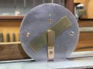
Here is my, RE THOMPSON GWR TRACK CIRCUIT INDICATOR / INSTRUMENT NUMBER 10.


Trying to scale up and draw this sketch from photos took me days my right eye gets very tired after a short time, I know there will be many if not all dimensions not to scale with each other but as long as the overall finished item looks convincing I will be more than happy,
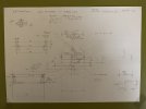
IMG_9825.jpeg


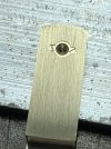
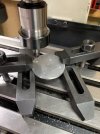
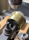
The Face plate is 4.6mm thick Aluminium, the hole saw seen here is 75 mm Dia.
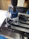
IMG_9827.jpeg


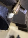
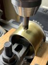
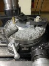
To bring the diameter down to the required size I used the rotary table the sections un cut under the clamps I filed down by hand.
The outside Diameter of the instrument casing is 70 mm with 1mm wall thickness so this disc is a little under 67 mm .
IMG_9831.jpeg


IMG_9832.jpeg


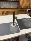
I lapped the surface using this old valve grinding tool that belonged to my father the suction cup has been replaced many times by me but the handle is original from the 1930s .
IMG_9834.jpeg


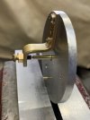
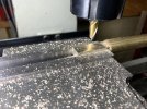
This is the start of the front bearing its the second attempt I ruined the first.
IMG_9848.jpeg


IMG_9841.jpeg


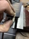
I used 1200 W&D to remove the cutter marks, the fine marks left by the machining on the original instruments change directions
on the bearing face, the bearing end which is the highest has the machining lines running lengthways with the bearing the lower
mounting section has the machining marks cross ways I've tried to do the same.
IMG_9853.jpeg


The second attempt lived.
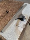
IMG_9851.jpeg
 

jonte

Western Thunderer
Magnificent modelling, David, and I’m in awe of your skills.

Sincerely sorry to learn of the failing vision in your left eye, but I admire your fortitude and ingenuity in overcoming it.

I shall continue to observe with the greatest admiration ;)

Good luck,

Jon
 

David Waite

Western Thunderer
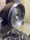
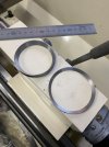
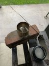
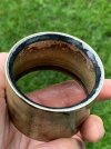
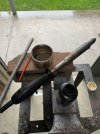
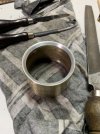
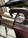
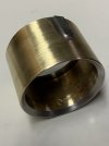
I have been enjoying making the various bits and pieces for this Instrument over the last week or so, the next two items I made were turned up out of this 75 mm piece of steel stock. First, the 70 mm diameter old Brass tube that I am using for the casing needs to look as if it has a rolled in front Beveled edge so a tapered insert needs to be made for this purpose, the Second item is the tapered Spacer piece between the glass and the Face Plate of the Instrument.
IMG_9864.jpeg


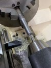
I bored the centre out using this 30.5 mm drill to allow access for the boring bar.
IMG_9865.jpeg


The spacer piece is finished and is being parted off.
IMG_9866.jpeg


Almost finished is the imitation rolled in front edge.
IMG_9867.jpeg


Both finished
IMG_9868.jpeg


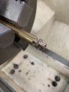
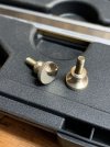
I needed two thumb screws that hold the Instrument on to its mounting bracket so I decided to make them for something to do
The knurl on the grip should be a straight knurl on these knobs but I have never owned a straight knurling tool I find Cross knurl better to hold onto when making punches ect as they don't slice mini groves in ones fingers, my knurling tool is a multi head one with three sizes and I chose the smallest cross knurl for these I think it looks ok.
IMG_9875.jpeg


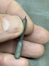
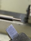
I cut a couple of brass screws down to act as threads
IMG_9881.jpeg


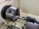
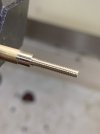
This afternoon I started to make the main Brass shaft this I turned down to 3.2mm Diameter from larger stock and then drilled a 0.85mm hole into both ends for the hard pivot spindles to fit into, my lathe is a bit big for this type of work there is no feel whatsoever on the drill bit all I can do is watch.
IMG_0185.jpeg


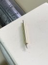
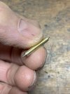
The pivot spindles were hammered lightly into place these are cut from straight sections of a spring they will be silvered into position then trimmed to length and the ends rounded to a smooth finish.
IMG_0186.jpeg


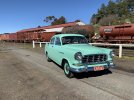
I will share something different this is my other interest.
I haven't driven my 1959 FC Holden (Standard Sedan) for about 5 months and since my eyesight has failed I've not wanted to drive it until I was feeling confident and in any case our weather has not been suitable. However yesterday was the first nice day for ages, it was a very frosty morning but had a clear blue sky and the sun was out and shining with a maximum of 13 C so my wife packed a picnic lunch and off we went, we travelled to Trentham for morning tea and walked along the old town Main Street looking at the shops apparently they reported the lowest frosty temperature on record at -8.5 C. Then onto the old gold mining town of Dalesford which is where this photo is taken, its a Tourist railway that runs a DERM and WALKER rail motor on most Sundays we had lunch sitting under the awning of the station building in the sun it was lovely, after lunch we drove a short distance into the town and walked along the Main Street which is full of old shops catering for the weekend tourists. We then traveled to the town of Vaughan Springs and over a couple of one car bridges to sample the Mineral Water which was running fast out off the pipe into the creek, its one of those places you wish the day would go on forever but it was a little chilly down in the valley so it was nice to get back into the car, I do have a original accessory Heater that I fitted it dosen't make the car hot but it warms the air a little and helps to demist the windscreen in spots when needed ( the quarter vent windows are better ) if you can stand the cold breeze coming in. From here we went to the town of Gilford and had afternoon tea in a lovely park then onto the old gold mining town of Castlemaine and again walked around the town centre by then it was getting close to 4pm so we headed in the direction of home.
We travelled a total of 143 relaxing miles and I recon my average speed was 47 mph its a good speed for the 6.40 cross plys and stopping with no power assisted drum brakes takes some distance, its powered by a 138 cubic inch (2.1 Ltr ) six cylinder OHV engine the low down torque is enormous for its size it has a 3 speed column shift gearbox.
Other than some of the chrome plating and grinding of the crankshaft and cam shaft journals I restored it all myself including the paint job in 1978 so I have owned it now for 45 years, all the mechanicals I replaced with new parts that I purchased from the dealers back then so its basically a brand new car in a old body, and in all those years its only done 27,000 miles.
IMG_0084.jpeg
 

jonte

Western Thunderer
Pleased, David, that your eyesight has restored enough to enjoy a wonderful sounding day out, especially since you managed to take along your pride and joy too ( and of course, your dear lady wife ;) ).

Fabulous lathe work too :thumbs:

Jon
 

Brian McKenzie

Western Thunderer
I have been enjoying making the various bits and pieces . . . out of this 75 mm piece of steel stock.

. . . it was a very frosty morning but had a clear blue sky and the sun was out and shining . . . old gold mining town of Dalesford. . . then onto the old gold mining town of Castlemaine and again walked around the town centre. . .
My kind of hobby work David, excellent stuff. :thumbs:

Just look at the clarity of atmosphere of the day out in the Holden car. We get that often in the South Pacific.
Spent several enjoyable days touring the same area, Ballarat to Bendigo, and Maryborough to Mount Macedon. Fascinated with the architecture, especially in Castlemaine.

-Brian McK.
 

David Waite

Western Thunderer
Pleased, David, that your eyesight has restored enough to enjoy a wonderful sounding day out, especially since you managed to take along your pride and joy too ( and of course, your dear lady wife ;) ).

Fabulous lathe work too :thumbs:

Jon
Hi Jonte
My eye hasn’t got any better it is just a case of getting use to what I cannot see and learning to judge the distance of where the car is, for example the LH side of the car when driving isn’t clear so sitting behind the steering wheel is a bit like riding a bicycle where there isn’t anything either side of you other than the bicycle underneath if I was driving a LH drive car I probably wouldn’t notice a difference other than what was out side, anyhow I recon I’ve mastered it I dodged many pot holes with flying colours. The dear lady wife supplied our lovely food, tea & coffee so that gave her a free ticket to ride
David.
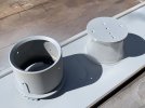
 

David Waite

Western Thunderer
Following on
The the pivot spindles were silver soldered into place the armature isn't being fitted to the shaft yet as I need the
plain shaft to balance the Banner, when the armature is finally fitted its weight will give the instrument its Fail Safe position.
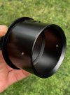
IMG_0191.jpeg


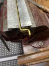
I bent up this washer to use as a radius template then filed the brass to suit.
IMG_9966.jpeg


All done
IMG_9972.jpeg


The 0.9mm spindle hole was drilled and the bracket mounting screw hole, the two large milled holes are for two locating dowels
to keep the bracket firmly in place.
IMG_9985.jpeg


On the front side I have made a imitation Spindle bearing including its retaining screws the 0.9mm Spindle hole is about 0.75mm on the other side of the counter sink hole point.
IMG_0002.jpeg


The two smaller holes which will be the fake screw heads were milled with a 1mm cutter, that was extremely difficult for me to see and do on the machine I just couldn't get a comfortable position to get a good focus, that has learnt me of this limit with my eyesight even with a two lens magnifier in front of my glasses and about 50 mm away from the milling collet as it was spinning around.
IMG_0015.jpeg


However I got there in the end.
IMG_0026.jpeg


Here is a Tip / Ramset nails are very hard and can be ground to any shape as a small punch, I ground this on the grinder then finished it on a stone
IMG_0035.jpeg


It only takes the weight of a small hammer to leave a shape
IMG_0042.jpeg


IMG_0040.jpeg


Most of the various holes were drilled / milled and counter sunk as required on both sides of the Face plate.
IMG_0048.jpeg


The rear Brass Bearing support Bracket being bent into shape.
IMG_0050.jpeg


I needed a diameter of a Cheese Head screw, of a size that looked correct for the front Bearing Bracket as I had nothing to suit I had to
make one, the thread is a metric 2.2 mm, the brass stock is 3.5mm diameter.
IMG_0197.jpeg


I made a threaded mandrill to hold the screw this to allowed me to turn the head to length.
IMG_0200.jpeg


My little screw I made can be seen sticking out, this will have a lock nut screwed on it at the final assembly.
This is the Balancing part of the build the end float of the shaft is adjusted for minimal movement.
IMG_0241.jpeg


The 16 Thou Banner was made by drilling the hole first then measurements were made outwards from the edge of the hole to the Banners dimensions this way I could get the hole exactly in the centre, it was all hand filed to size and finished with 1200 W&D the little blue dot is to keep the Banner positioned the same way around as it had to be removed many times to sand small amounts off to get a perfect balance.
By getting a perfect balance less magnetism is required to move it therefore less voltage is needed to run the coil so the coil runs cooler.
IMG_0277.jpeg
 

David Waite

Western Thunderer
I have been really busy over the last five days and I have made great progress with the build
The Face plate was stripped down and the first thing to do was to Silver the Armature to the shaft this was
done using one of the jigs that I made for the construction of Lever Frame which I still hadn't thrown away lucky I didn't.
IMG_0249.jpeg


All cleaned up
IMG_0251.jpeg


Next job was to make a Aluminium bracket to hold the Coil in place
IMG_0293 2.jpeg


The tricky bit is to get the Coil and Armature in their correct position so the Banner stops in its correct position on
the front side of the Face plate.
IMG_0295.jpeg


The making of the Springs
Lucky I have a large roll of spring wire of this size because to get the Two springs I needed I ended up with
a pile of failed attempts, both springs are different there is a L/H and R/H spring coil and the single coil
that raps around the 10BA screw is reversed on the lower spring there is also a dog leg on the short section
between both coils to lift the spring coil off the face plate by a small amount.
This is the final Top spring being made, both coils are on the same side.
IMG_0308.jpeg


This is the Lower spring and as can be seen the coils are on opposite sides.
IMG_0310.jpeg


The angle of the springs seem to differ between Instruments of the same type I believe due to the variation of screw positions and the
position of the word OCCUPIED which needs the Banner to stop in a position to cover it.
IMG_0312.jpeg


IMG_0333.jpeg


Next job is to Silver the steel cone into the Brass casing.
IMG_9960 2.jpeg


This was Silvered from the inside but with no build up allowed on the steel cone as the glass must sit flat up against it.
IMG_0339.jpeg


Done.
IMG_0343.jpeg


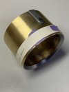
Next was to soft solder a bead of 50/50 solder around the top edge so I could file this to a nice rounded corner.
IMG_0344.jpeg


All done, scraped / filed and sanded to a smooth finish
IMG_0351.jpeg


The Bakelite casings have a flat section that the Thumb screws pass through and tighten up against, these
I have reproduced with small pieces of galvanised iron which I soft soldered to the Brass casing.
IMG_0352.jpeg


IMG_0354.jpeg
 

David Waite

Western Thunderer
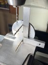
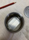
I placed two drill bits into the horizontal face plate mounting screw holes, this is so I could square up the face plate and to use
them to give me two hole positions either side on the outer edge of the face plate in the same centre line as the drill bits, these holes will be tapped 2.2mm and are to hold the mechanism in place within the casing.
IMG_0379.jpeg


Next was to mark the positions for the Two holes in the casing which have to line up with the two holes in the outer edge of the
Face plate these positions were also governed by the thickness of the glass and the spacer ring.
IMG_0369.jpeg


Clearance drill for a 2.2mm screw
IMG_0376.jpeg


Counter sinking to a fraction over 4mm Diameter.
IMG_0378.jpeg


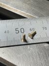
Once again I didn't have any 2.2mm brass counter sink screws to suit so Two had to be made the heads were turned to
a diameter of 4mm.
IMG_0381.jpeg


This is how I slotted the screw heads,
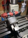
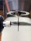
The clamp holds the moto tool firmly which is held in the vice I then jammed a timber wedge under the drive pulley of the spindle up in the belt housing to prevent the chuck from moving, I then use the Y Axis to run the cutter back and forth across under the
screw head and at the same time lowering the down feed -Z Axis- little at a time to give me the slot depth I require.
IMG_0393.jpeg


Its impossible for me to set this up with a dial so I just put some round stock in the chuck and do a trial cut I then remove
the stock and measure the test slot to the outside of the stock and a adjust the X axis to give me the centre position of the cutter,
the abrasive discs often don't run true and vary in their thickness so a little give and take is often required and if it doesn't work
out perfect I don't mind as slots in screws are often off centre.
And my phone camera has now become my second pair of eyes
IMG_0397.jpeg


These eventually will be painted Black.
IMG_0421.jpeg


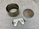
The Instrument needs a mounting bracket this I made by hand out of Aluminium.
IMG_0430.jpeg


The good thing about Aluminium is the quickness that bits and pieces can be made.
IMG_0431.jpeg


The Bracket is a firm sliding fit into the casing.
IMG_0432.jpeg


I drilled and Tapped the Bracket 1/8WW for the Two thumb screws that hold the casing on, the V shape cutout is to clear the coil terminals and the Main Spindle adjustment screw.
IMG_0436.jpeg


First coat of Etch primer, and if you are wondering what is the screwed on piece that is attached under the casing this was a part of what ever the casing was originally used for, I'm not going to use it but it has come in handy for holding the casing throughout the build.
IMG_0439.jpeg
 

David Waite

Western Thunderer
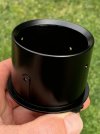
Things are going a bit slow at the moment just waiting for each coat of paint to dry, our weather has been a bit cold of late so
I had to leave each coat a couple of days before sanding and re-coating but I got there in the end.

Top coat finished
IMG_0534.jpeg


IMG_0532.jpeg


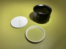
The Face plate and Spacer ring are also finished I will let the paint harden a little longer on the Face plate before I put the lettering on.
The air brushed White paint is Tamiya full gloss Lacquer, after the lettering is applied I will spray all the white surfaces with a satin clear coat.
IMG_0539.jpeg


I Nickel plated the two springs I made, being so small and thin it only took 60 seconds to put a good coating on each.
IMG_0526.jpeg


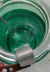
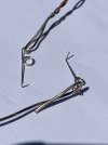
I will leave them on the copper plating wires until I'm ready to install them at least I know where they are as they would be easily lost.
IMG_0587.jpeg
 
Top