A Layout Called CHIMTONSTOKE

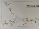
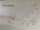
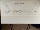
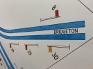
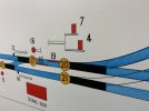
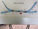
Drawing of the SIGNAL BOX DIAGRAM

David Waite

Western Thunderer
Now that the Compass had been made I could continue on with the Diagram.
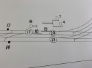
The reason for the use of the Tracing paper for the trial sketch was only because it is easy to remove mistakes with an Eraser so nothing to do with tracing. The Compass worked a treat, it took many attempts to get the sketch correct as allowance had to be made for the the Signals to fit as these are 46mm long with a spacing of 25mm and so both junctions were moved a few times as well as the alignment of the main lines and naturally the radius of all the tracks changed slightly each time for both, as each radius was done I circled the Needle hole with a pencil and wrote the radius next to it.
When I was finally happy with the track work I cut up pieces of thick card and taped it over where the Needle point holes were, I then went over each radius again with the Compass and once correct I pushed the Needle into the card leaving a new Needle point hole, now that I knew these card pieces worked and maintained the correct position and without the Needle point going through them I removed these small pieces of card and replaced them with better ones, some of them I replaced with longer ones these were taped firmly to the drawing board away from the tracing paper and laid gently across the top of Tracing paper with a new Needle point hole placed in them at the correct position.
The idea behind this is so I could un tape the Tracing paper and slide it out from under the card and replace it with the Digram paper by sliding this back under the card pieces.
The other reason for the card was to prevent any holes being put into the final Diagram drawing

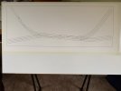
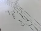
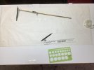
This shows the completed sketch in pencil [0.3mm] and the test pieces of card for the pivot positions of the Compass
IMG_1994 (1).jpeg

The paper that I used for the Diagram is made in France by ARCHES its a Hot Pressed 360 gram Acid free Cotton Fibre paper, I chose this thick paper to help prevent any buckling of the Diagram from the likes of moisture.
I didn't take any photos of the Diagram with only the pencil lines as they didn't show up very well on the white paper.
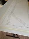
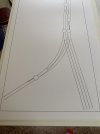
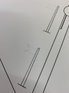
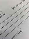
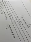
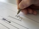
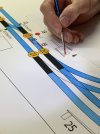
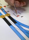
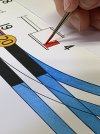
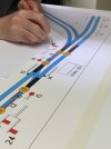
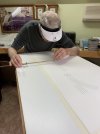
In this photo I am slowly Inking over each pencil line with the permanent Ink pen trying to keep my shaky arms still, this kept my nerves on edge I was glad when it was done, in this photo most of the card pieces have been removed as the lines were done and they were no longer needed.
IMG_4685.jpeg


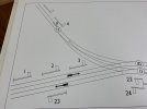
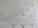
First major stage done.
IMG_4688.jpeg


IMG_4689.jpeg


IMG_4690.jpeg
 

David Waite

Western Thunderer
The next stage was to draw all the Signals and other items including all the Numbers and Letters all in pencil then
once this was done every thing was very carefully inked in with the permanent Black Ink pens
IMG_4908.jpeg


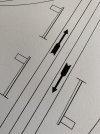
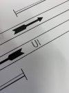
The UP & DOWN Track Direction Indicators
IMG_4915.jpeg


IMG_4916.jpeg


IMG_4918.jpeg


IMG_4910.jpeg


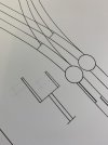
The Ground Signals are drawn to the outside of the rails and this is where they will be positioned on the Layout not in the Six Foot as was the norm in later years.
IMG_4913.jpeg


After all the pencil lines were inked in then came the task of filling everything in.
IMG_4925.jpeg


IMG_4937.jpeg


The shape of some numbers were tricky to do the numbers 2, 4 and 5 I found the hardest.
IMG_4939.jpeg


Probably the easiest Signal Box I will ever Build
IMG_4940 2.jpeg


IMG_4936.jpeg


IMG_4962.jpeg


The spacing of letters is a form of art, for me its just trial and error spacing each letter until it looks correct next to the others.
IMG_5369.jpeg
 

David Waite

Western Thunderer
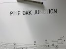
I left the Signal Box name to last, in this photo I was working on the letter O in OAK, slowly inking around the inside curve on the upper L / H corner only a few mm to do and the O will be finished.
IMG_4952.jpeg


One of the few memories that I have from when I was a child was sitting on the floor in our back verandah filling in pictures in little book with water colours, the various colours were small hard blocks of paint separated in a thin flat pressed tin casing, when I rubbed a wet brush on them they melted and would fill the Bristles with paint, it must have meant a lot to me as I still remember.
So now moving into the future to 2022 which was regarded as space age back then, I was going to attempt water colours again.
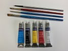
I purchased brushes that I thought would suit me [which did] and water colour paints that I needed all shown in the photo below, I then practiced on some off cuts from the cotton paper.
IMG_9378.jpeg


The first colour that I applied were the simplest, Yellow to the Distant Signals and the Point numbers, this gave me a feel on how things were going pan out.
IMG_5372.jpeg


IMG_5373.jpeg


IMG_5371.jpeg

After the Yellow colouring was done I didn't take photos of the Track colouring as I didn't want to be distracted and then forgot to take some between each stage of the progress. First I did the lie of the points in Black, I then coloured in the track work with Blue that I mixed with a little white to lighten it down. It was for me extremely difficult to obtain a uniform Blue colour along the long uninterrupted lengths of track work and especially without going over the black edge lines which I managed, so what I ended up with was the best I could do which I was pleased with.
Next was the Red colouring which was Fun as it was finally coming to life.
IMG_5378.jpeg


IMG_5380.jpeg


IMG_5386.jpeg


IMG_5392.jpeg


IMG_5410.jpeg


IMG_5412.jpeg


After all the colouring was done and I had checked it many times and looked at it many times, I took a photo and sent it to a signalling friend who picked out a missing piece of colour straight away it just goes to show you some times its good to have a second set of eyes, anyhow out with the water colour and it was quickly sorted. [ It was the section of track between points 21 and the Diamond how on earth I miss that! ]
IMG_5411.jpeg


FINISHED
IMG_5428.jpeg
 

David Waite

Western Thunderer
It is exquisite.

I would not consider doing it by hand, as I’d make a mistake, and then have to start again, as covering up is never going to work. And I don’t have the patience.

it is nice to see stuff ”done the hard way” so beautifully.
Thanks Simon
l must admit my nerves were on edge as any mistake would mean ruin and with my eye sight the way it is I checked each next move a few times and made sure I was comfortable before the permanent ink or water colour was applied.
David.
 

J_F_S

Western Thunderer
Lovely work David - I think your skills might be in demand by not a few heritage societies!

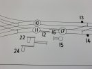
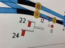
Just one thing puzzling me - what is the purpose of FPL 16 (double ended FPLs are a bit of a nightmare!)? [and apologies if you have already explained that and I have missed it in the thread!]

Best Wishes,
Howard
 

David Waite

Western Thunderer
Lovely work David - I think your skills might be in demand by not a few heritage societies!

Just one thing puzzling me - what is the purpose of FPL 16 (double ended FPLs are a bit of a nightmare!)? [and apologies if you have already explained that and I have missed it in the thread!]

Best Wishes,
Howard
Hi Howard
FPL 16 well spotted, these would not normally have been fitted on a trailing crossover, of course all facing points have to be fitted with a FPL if it was used for passenger working, I have included them to allow the odd passenger train with a one or two coach train coming off the branch onto the Down and then proceeding onto the Up via the crossover with signal 18 to continue its journey towards Chimtonstoke, and a weekly push pull workers train from Coalchester on the Up changing direction at Pine oak Junction via the crossover with signal 15 to Bridgeton on the Down, there was no other reason for adding them other than that, and it saves the 4 mm signalman from clipping the points on a very busy mainline this is my excuse, it did however give me another FPL lever to add to the frame and it didn’t add much to the interlocking and will add a bit more fun.
David.
 
Last edited:
Frame for Pine Oak Junction Signal Box Diagram

David Waite

Western Thunderer
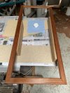
I hade two attempts at making a frame, my first attempt was making a frame out of a piece of Mahogany that I had, it was wide enough but its ruff sawn thickness was not much more than the finish size I wished for, however I decided to machine it up to see if it looked ok once it was finished, but no it looked to thin and was out of place so this will get turned into a frame for my wife to use.
I started looking in amongst the timbers that I have not expecting to find anything but lo and Behold there was a piece of Merbau about six feet long standing hidden in a stack. I measured it up and allowing for the blade thickness and minimal machining it would do the job nicely.
Merbau is a heavy timber, its used nowadays as a replacement for Jarrah [ but its not as good as Jarrah ] and used for window sills Door sills and Decking.

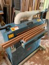
The piece of Merbau was cut into four pieces squared up and trimmed almost to size in the Thicknesser, it was then run through the Drum sander to give the final size and a smooth finish, it has a tendency to char the fine belt due to the oil in the timber however it doesn't affect the course belt.
Squared & finished to size.
IMG_7910.jpeg


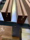
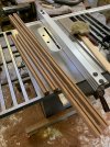
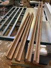
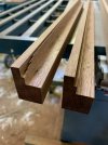
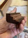
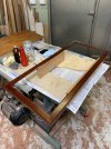
The frame isn't made as a normal frame would be made I have rebated [ stepped ] various levels, First the glass, Second for the 3.8mm matt board spacer & inc Diagram with its 3.8mm Matt board backing and Third for the rear 3 ply backing.

First stage of the Rebating done on the table saw.
Those slivers are just less than one mm
IMG_7913.jpeg


IMG_7911.jpeg


IMG_7914.jpeg


IMG_7916.jpeg


The end result
IMG_8524.jpeg


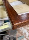
Like normal I got so caught up in the build I forgot to take photos of the assembly, the corners are just Butt Mitred glued joints however my research has turned up various ways these corners were held together some simply nailed through the end sides, some with a wood screw entering through the end sides and some with a metal bracket as a extra hold at the rear of each mitred corner. There are of course other ways that the corners were made such as Mortise and Tenon ect but I'm only concerned with the Mitred joint type.
IMG_8073.jpeg


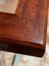
From the outset I wanted to French polish the finished surface which I did, this is done with many thick grain filling coats and many '30 plus' thin finishing coats of amber Shellac this was done to the sides and both chamfers of the frame only and are to a mirror finish.
The face surface has no grain filling but the fine sanded flat finish on it has 31 coats this gave a contrast to the sides and it prevented the face from looking fake [ its the only way I can describe it ] I was very pleased with the result.

Slowly applying the Shellac.
IMG_8467 2.jpeg


The open grain of the Face surface can be seen in this photo, many of the smaller grains filled but the larger ones remained which is what I wanted.
Merbau has Sliver streaks and with lots of other shades/colours that are richly enhanced with the Shellac.
IMG_8491.jpeg


As can be seen I used wood screws to hold the corners which some frames had, of course I don't really need them but they look good and at the same time gives an extra holding force.
IMG_8496.jpeg


This photo shows where the rebates are positioned on the under side of the frame.
IMG_8522 2.jpeg
 
Last edited:

simond

Western Thunderer
I'm not sure if this link deserves to be in such august company, but I needed to do a diagram this week. Tis here


David Waite

Western Thunderer
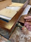
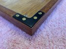
As I mentioned before some frames had small angled brackets at the corners on the rear of the Frame as a extra support for the mitred corner joint [GWR] I'm not sure if all of their mitred frames had these or just some, if anyone knows about this please do tell.

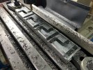
I'm afraid I couldn't help myself and I just had to represent them, a photo that I have shows these small angled brackets having tapered sides which normally would indicates a casting not a stamped out product and the inner corner has a radius which is something one would do for soft metal so I'm thinking these brackets might have been cast in Brass but I could be wrong.

I needed some metal so I used a piece of 25 x 50 all gal RHS this also saved trying to hold the individual pieces in many ways for each milling operation.
IMG_8005.jpeg


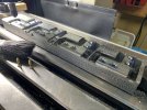
The brackets were completely finished only being held by a thin piece of un cut metal along the front edge "nearest to the camera" and the short edge at the rear, this short edge was the first to be fully cut through then I just wobbled the front edge back and forth until it broke free.
IMG_8007.jpeg


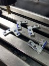
Ready for cleaning.
IMG_8009.jpeg


All cleaned up,
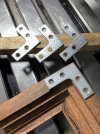
Next to spray them with a etch primer then a Black Satin top coat to finish.
IMG_8015.jpeg


Finished
IMG_8668.jpeg
 
Top