A Layout Called CHIMTONSTOKE

simond

Western Thunderer
David,

I can only applaud your results, your evident craftsmanship, and your patience.

I’m essentially a lazy b….r and want maximum results with minimal effort, so embraced computers as a means of achieving this at the earliest opportunity!

(Of course, it still requires effort, it’s just that nobody can see your rubbings-out)

enjoying your thread very much
Simon
 

Dog Star

Western Thunderer
I have restored the cases of GWR, LSWR and MR block instruments and I think that gives me a green light to say that the quality of your work is astounding.

Thank you for sharing and for explaining how the various instruments interwact.

regards, Graham
 

ovener

Active Member
Truly inspiring work there David. Thank you for sharing it with us. I think in my mind I would create something like this, but the reality is beyond me.
 

David Waite

Western Thunderer
David,

I can only applaud your results, your evident craftsmanship, and your patience.

I’m essentially a lazy b….r and want maximum results with minimal effort, so embraced computers as a means of achieving this at the earliest opportunity!

(Of course, it still requires effort, it’s just that nobody can see your rubbings-out)

enjoying your thread very much
Simon
Thanks Simon

You said you want maximum results with minimal effort, in the modern work force that’s called
Work Smarter Not Harder nothing wrong with that, if you can why not.

David.
 

David Waite

Western Thunderer
I have restored the cases of GWR, LSWR and MR block instruments and I think that gives me a green light to say that the quality of your work is astounding.

Thank you for sharing and for explaining how the various instruments interwact.

regards, Graham
Hi Graham
It’s a pleasure to share with you and all on WT that is after all what it’s all about.
I am slowly reading my way through WT and what I have seen and read is amazing.

You are very lucky to have had the privilege of restoring such beautiful Instruments I envy you, one of my projects that is on hold at the moment is building a Full size GWR Signal Arm Repeater Instrument that was made by Walters electrical Co for the GWR, the mechanism has been finished and in full working order the next stage will be the building of the mahogany case, I have also made the mechanisms for two Tyers Signal Arm Repeater Instruments again full size that also require cases so I will build all three together.
David.
 

David Waite

Western Thunderer
Truly inspiring work there David. Thank you for sharing it with us. I think in my mind I would create something like this, but the reality is beyond me.
Thanks ovener

I think the same when I see people 3D printing small items with their computers that my eyes could never see clearly to even build by hand, some things are just beyond me to. However I always told the apprentices to have a go no mater how it turns out, perhaps there’s a message in that somewhere.
David.
 

David Waite

Western Thunderer
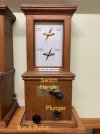
WINTERS BLOCK is a easy system to work, the official Rules of their operation can be a bit confusing and many find it hard to grasp.
I will put in my own words the Sequence of Operation [1to 9] and * What is happening, which the official rules doesn't mention.
Note the SWITCH HANDLE can also be called the COMMUTATOR same thing different name.

Lets start with Two Signal Boxes A & B
Where A wants to send a DOWN Express Passenger train to B

1/ Signalman A calls Attention to B with ONE beat on the PLUNGER * this rings the Bell Once in the Instrument at B.
2/ Signalman B acknowledges this by giving One beat on his PLUNGER * this rings the BELL Once in the Instrument at A.
3/ Signalman A then asks B "is line clear for a Express Passenger Train" by giving Four Beats on his PLUNGER
* this rings the Bell Four times in the Instrument at B.
4/ If Signalman B can accept the train he Puts his SWITCH HANDLE to TRAIN ON LINE and gives Four Beats on his PLUNGER
* this rings the Bell Four times in the Instrument at A.
*Signalman A now knows that Signalman B has accepted the Train.
5/ Signalman A Pushes in his BLACK BUTTON while holding it in he then gives One Beat on his PLUNGER
* this rings the Bell Once in the Instrument at B and at the same time this MOVES BOTH DOWN LINE NEEDLES at A & B to
DOWN TRAIN ON LINE.
6/ As the Train passes into the section from A, Signalman A gives the Bell Signal "Train Entering Section" with TWO Beats on his PLUNGER
* this rings the Bell Two times in the Instrument at B.
7/ Signalman B acknowledges this by repeating it back to A by giving TWO Beats on his PLUNGER
* this rings the Bell TWO times in the Instrument at A.
8/ When the Train arrives at B and is complete Signalman B Puts his SWITCH HANDLE back to LINE CLEAR and gives the Bell signal
"TRAIN ARRIVAL" with THREE beats on his PLUNGER
* this rings the Bell THREE times in the Instrument at A.
9/ Signalman A on Receiving the THREE Bells Pushes in his BLACK BUTTON while holding it in he then repeats the
"TRAIN ARRIVAL Bell Signal with THREE Beats on his PLUNGER
*this rings the Bell THREE times in the Instrument at B at the same time this MOVES BOTH DOWN LINE NEEDLES at A & B to
DOWN LINE CLEAR.


IMG_8432.jpeg
 
DOUBLE LIFT UP SECTION

David Waite

Western Thunderer
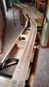
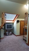
My Baseboards have Two walk through areas one has a Single Lift up Section the other is a Double Lift Up Section one half is Automatic the other is manual reason for it being Double is I need the open space with both Sections up in the air to have a unhindered view of my Television which is under the roof window and also gives a bigger open area to walk around.
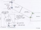
I have drawn a sketch of the Two Sections to accompany the text which will show and explain the design better.
The Automatic side [ Motor Driven ] Butts to its Base Board squarely so normal hinges shown as Hinges A [ in Green ] could be used.
The Manual side is Different the Base Board on this side is square however the Manual Lift up Section that connects to it runs off on an angle from the Base Board end so if normal hinges shown as B [ in Blue ] were to be used the Lift Up Section would rise on a angle and block off half of the walkway as shown on the sketch, so I came up with a way of making the Manual Lift Up Section rise in a upright position using Automotive Suspension Ball Joints shown in Pink on the sketch. These Ball Joints can pivot in any direction which is what is needed as the arm that connects to the lift up section not only pivots in the way a hinge dose but also Twists as the Lift up section moves from horizontal to its vertical position.

Scan 24.jpeg


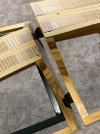
The Lift up Sections are made from Pine with Steel frames incorporated into their design to give strength and keep them true the actuating arm from the Drive Gear box also connects to the Steel frame on the Automatic side, the Hinges on the Automatic side are fabricated from steel with Ball races as the bearings and are connected directly to the Steel frame. Where the Two Section meet there are Dowel pins to keep side way movement within a couple of Thou these pins locate into slots that can allow opening movement of the rail gap for expansion of the two sections which is minimal throughout the year.
20200514_162057.jpg
20200514_161707.jpg

20200614_155237 (1).jpg
 

David Waite

Western Thunderer
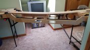
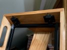
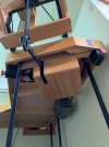
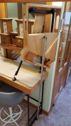
The two sections here in this view are kept in the horizontal position by the adjustable Stainless steel support pole which is supporting the Manual Section only shown on the Right Hand side. The pole has a movable joint fitted into both ends, the top end is connected to a bracket that protrudes through the timber ply cover on underside of the Manual Section, the movable joint on the lower end of the pole connects to the cross beam that is connected to Base Board support legs.
20200514_161146.jpg

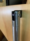
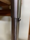
The Top movable Joint on the Manual Section Support Pole is a interference fit into the tube and is pined
with a roll pin. The section of the joint that is pressed into the tube is solid and is about 25 mm long this acts as a STOP
which the internal Lower sliding tube pushes against when the Lift up Section is Lowered into its horizontal position.
IMG_8367.jpeg

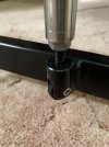
The lower end of the Support Pole Joint is Adjustable to set both Lift up Sections in a Horizontal position
IMG_8364.jpeg


The Lower internal sliding Tube has a Spring loaded Push Button this is built into a solid piece of Stainless Steel
which acts as a STOP that pushes against the STOP that is in the top of the Outer tube. the Push Button keeps
the lift up section raised in the upright position.

IMG_8365.jpeg


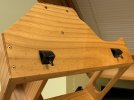
The Two Locating Dowels on the Automatic Section.
IMG_8341.jpeg


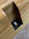
The Manual side showing the slots that the Dowels locate into.
IMG_8346.jpeg
IMG_8347.jpeg

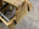
The rear view, The Slots are screwed to the Timber end as a seperate item and then screwed to the Steel Frame.
IMG_8344 2.jpeg

Almost Locked together.
IMG_8348.jpeg


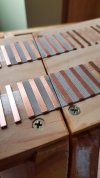
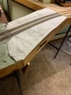
The gap varies throughout the year due to expansion and contraction but minimal, the Sleeper end pieces
are Milled out of PCB giving a solid fixing at the rail end Ballast will cover the Milled gaps between the sleeper
sections the joint should be almost invisible.
20200614_155430.jpg
 

D6356

Western Thunderer
An elegant and well engineered solution - work of art stuff. The milled sleepers a neat way of doing the join in such a visible location. I guess bottom of embankment scenic detailing could have an anti - fall kerb of stout bushes just in case, it would be a crying shame for a gravitationally inspired incident to affect a train of any kind.
Rest of layout looks inspirational as well, thanks for showing.
Robert
 

David Waite

Western Thunderer
An elegant and well engineered solution - work of art stuff. The milled sleepers a neat way of doing the join in such a visible location. I guess bottom of embankment scenic detailing could have an anti - fall kerb of stout bushes just in case, it would be a crying shame for a gravitationally inspired incident to affect a train of any kind.
Rest of layout looks inspirational as well, thanks for showing.
Robert
Thanks Robert
Thoughts of some sort of safety "anti - fall" as you said often cross my mind I do like the idea of stout bushes as you have suggested.
David.
 

David Waite

Western Thunderer
Milled sleepers, what a good idea. Did you lay them when the boards were together then cut them?

Thomas
HI Thomas
I placed the un cut length of Milled sleeper where I wanted it and drew a mark with a straightedge where I wanted the cut and removed them from the board to cut and file smooth, this way I could put them back in position a little closer for a smaller gap than the saw could give.
The Single Lift Up Section which I will show soon has the cuts done totally different.
David.
 

David Waite

Western Thunderer
Safety First /
The Closing join between the Two Lift Up Sections could cause a injury to fingers-hands or what ever else that could get stuck between them,
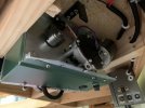
this was a easy fix with a Slot in the second arm instead of a bolt hole . The Motor & combined Gearbox started out life as part of a Swing Gate unit before I hacked it into something I could use, it is capable of moving Swing Gates up to 350kg of course its lifting capabilities are no where near that.
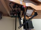
There are Two arms, one attached to the output shaft of the Gear Box about 450mm long with a 10mm bolt through its outer end, this bolt passes through a 10mm wide 65mm long Milled Slot in the lower end of the vertical 500mm long second arm, the top end of this arm is attached to the Lift up Section.
As the gear box drives the first arm to raise the Lift Up Section the Bolt rides against the Top of The Slot in the second arm, naturally as the Lift UP Section is lowered its weight and gravity holds the slot in the same position until it comes to rest on the Dowels, at this point the Limit Switch stops the Motor, the slotted arm stops moving but the bolt moves onward a little due to the motor slowing down and moves slightly away from the top of the slot which allows the full weight of the Automatic Section to rest on the Manual Section without force from the Motor.
The Automatic section can now be lifted up 110 mm by hand until the Bolt hits the bottom of the Slot, so the crushing force is only the weight of the Lift Up Section not the force from the Motor & gearbox.
There is One other Safety by way of the Control Switches. When the UP button is pushed [note the Down Button is taken out of circuit] the Lift UP Section continues to rise until it is stopped by the Limit Switch or by the Emergency Stop Button, but when the DOWN BUTTON is pushed and the Lift UP Section is Lowering at any point the UP BUTTON can be pushed and the Motor will change direction Immediately and Raise the Lift UP Section and continue until it stops by the Limit Switch, of course the Emergency Stop Button will also stop the Motor in the Down Direction.


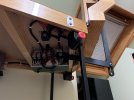
Here the Slot can be seen in the Vertical Second Arm.
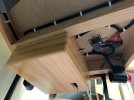
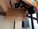
The Motor & Gear Box is under the timber cover.
The Two Red Buttons are Emergency Stop Switches that have a Twist Release to reset them, the Metal housings
that the switches are in I made out of 20# Galvanised Iron and flame welded together .
The Two Push Button switches on the Stainless Steel Escutcheon plate are the Up & Down controls.
IMG_8305.jpeg

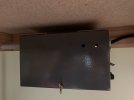
This box I made out of 20# Galvanised Iron and Flame welded together it houses the power supply battery, the light that can be seen
is the Battery Charging Indicator the other hole shows the Battery FULL Indicator.
IMG_8296.jpeg

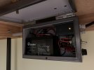
The 12volt 9AH SLA battery and the Solar Charging Regulator which is in the charging mode.
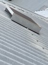
The Grey conduit to the Left is taking the cabling to the Solar Panel outside on the roof.
IMG_8300.jpeg

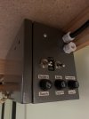
Fuses everywhere I like fuses
IMG_8297.jpeg
 

David Waite

Western Thunderer
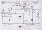
Here is the Electrical Diagram for those that might be interested in how it works.

Scan 29.jpeg


The Solar Panel out on the roof
IMG_8632.jpeg

Underside view showing the Momentary Reset push button switch for resetting the Safety Limit Switches these if they trip.
IMG_8303.jpeg
IMG_8302.jpeg

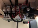
I mounted all the relays on the chassis to save having another electrical inclosure.
IMG_8308.jpeg

The Two steel Cams I made are shown in the Diagram as the UP & DOWN Cam switches these control normal operation.
The motor has its own Current Overload Protection and is the red button next to the fuse mounted on the underside of the gearbox cover.
IMG_8320.jpeg

UP position.
IMG_8331.jpeg

DOWN position.
IMG_8334.jpeg
 
SINGLE LIFT UP SECTION

David Waite

Western Thunderer
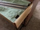
The other access near the chimney only needed a Single Lift up section however the small walk through created a couple of issues that needed to be overcome to make it user friendly not just for me but also the railway.
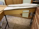
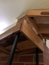
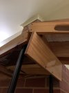
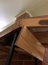
Firstly the Lift up Section needed to lift and move over the top of the board it is attached to so the walk through gap isn't reduced by the thickness of the lift up section when it is in the vertical open position, this was achieved by making under slung hinges these are made from 20mm 20mm RHS, the hinges are also level with the base board surface so they don't get in the way of the track work. I seen this type of hinge many years ago in a magazine and never forgot it. By using RHS the cabling can be put through them neatly and out of harms way.
The second issue is that Clothing could get caught on the Protruding rail ends as you walk through the gap however that was a easy fix, the following photos will tell the story.


IMG_8746.jpeg


IMG_8715 2.jpeg

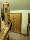
As can be seen the Lift up Section is completely clear of the walk way, its over centre of weight keeps it upright.
A piece of Timber is still to be fitted across the two vertical sections of the hinges this will protect the rail ends on the base board
and allow one to slide past and not get caught up on the hinges.
The single track on the Lower Left is the Branch Line to WAITECOTT.
IMG_8717.jpeg

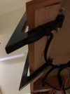
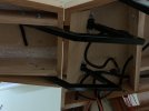
Under side view in the Raised Position showing the cabling entering the RHS to the Rails.
A solid piece of square steel is fitted into the ends of the RHS this has a steel pin as a pivot and is fitted into the other half
of the hinge which is bolted to the base board.
IMG_8720.jpeg

In the Lowered Position
IMG_8721.jpeg


The Rail End Protector this is lowered by the Lift up Section pushing down on it as it as the Lift up section is lowered into place.
IMG_8730.jpeg


The next 3 photos show the Rail End Protector being pushed downwards and out of the way.
IMG_8725.jpeg


IMG_8726.jpeg


IMG_8727.jpeg


There is one spring that pulls the Rail End Protector up wards the spring tension is only strong enough to do the job and a little more
it doesn't interfere with the Lift up Section this being just to heavy with the plaster on it
IMG_8722.jpeg
 
Top