You are using an out of date browser. It may not display this or other websites correctly.
You should upgrade or use an alternative browser.
You should upgrade or use an alternative browser.
A Layout Called CHIMTONSTOKE
- Thread starter David Waite
- Start date
Threadmarks
View all 19 threadmarks
Reader mode
Reader mode
Recent threadmarks
A NEW CHALLENGE IN LIFE Terminal Contacts for the Double Lift up Section The Adjustment Linkage ENAMEL NUMBER PLATES TYERS , SIGNAL ARM REPEATER INSTRUMENTS GWR TRACK CIRCUIT INDICATOR MADE BY WALTERS ELECTRIC MFG Co LONDON NEW Build / GWR Track Circuit Indicator Track LayingDavid Waite
Western Thunderer
Thanks Julian
David.
David.
David Waite
Western Thunderer
Thanks Ken
David.
David.
michael080
Western Thunderer
Very, very impressing.
I think I would put some protection around the levers clumsy as I am.
Michael
I think I would put some protection around the levers clumsy as I am.
Michael
michael mott
Western Thunderer
Inspirational work David, you have set a very high bar indeed. Like Ken has already said Wow is not enough!
Michael
Michael
David Waite
Western Thunderer
Just finishing off on the Control Panel for now until I progress some more on it.
There will be over one hundred wires that join the Control Panel to the layout and are all approximately 3 meters long, the first bundle is full which can be seen in the photo there will be another of the same size and one smaller, these terminate in a old original Terminal / JunctionBox I restored. These beautiful boxes were mounted high on a internal wall close to the ceiling in a room of a station building that had the Telegraph & signalling equipment and Telephones ect in it, there was a short length of timber Conduit that joined the box to the ceiling which all the wires went through in a bundle this bundle was loosely laid across the ceiling timbers in the roof space and often exited through a hole in a weatherboard gable, there was a tie wire that was tied off on a metal bracket mounted on the outside of the gable or wherever , this tie wire ran through the air to the closest line side Telegraph Pole which the bundle of wires was attached to. I made up a black panel to fit into the box on its original mounts, on this panel I have attached the terminal strips that the layout wires will join to.
David.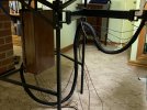

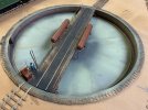
4mm BALANCED type TURNTABLE with Cowans Sheldon, Vacuum Tractor.
David Waite
Western Thunderer
I built my TURNTABLE in 1987 but the seed had been sown back in September 1980 when I picked up the latest edition at the time of Model Railways which had this entire edition dedicated to Frank Dwyers Borchester Market. A few things I read about his layout inspired me, One was working signals , Two was hand made track and Three was to build a turntable that was accurate in its operation.
My TURNTABLE is based on the LNER type ( Kings Cross ) but I have put the Vacuum Accumulators above the decking not underneath.
The only way I knew to make something accurate and solid was to build the pit out of STEEL so I did, I weighed the complete TURNTABLE assembly the other day and it weighs 12.6 Kg that's not a Typo that's 27.78 Lbs.
The pit base is made from 10# Black Iron (1/8"thick ) this I Gas Axed out of a square sheet to a dimension slightly larger than needed to allow for the pit wall to sit on and be welded to , immediately the disc dropped I poured cold water around its outer edge this causes the disc to shrink and take on a concave shape. A strip of 10# was cut for the pit wall and a thin strip was cut and curved into a circle for the top lip this supports the Pit on the Base board and is what the Coping and the outer ring of timber walking boards are fixed to.
The welding was all done by Ark there were 12 / 2.5 mm electrodes used in total, the pit wall was tack welded to the disc complete with the Table access service hole then the top lip tacked welded to the wall then fully welded with no distortion within 1mm when cooled. I was able to use any machinery after hours where I worked so long as I put everything back as I found it ready for the boys in the morning, one evening with the aid of the crane I swapped over and put a four jaw 2' chuck onto the 12' MAXSON lathe, I turned the lip and pit wall and machined a flat section on the disc near the base of pit wall for the pit Track Rail to be soldered to and machined out the centre hole, I then reversed the pit on the chuck and machined off a flat section on the underside around the centre hole for the bearing housing to be mounted against and then trimmed the disc edge and machined the underside of the lip.
The Table girder frame is made from 0.012" tin plate with brass sections soldered on to finish it off, the decking is Balsa wood and hand rails are brass. The Code 70 rails are soldered to small pieces of copper clad which are fixed to the cross beams. There is a Collet soldered to the centre section between the main frames which clamps tightly to the hardened main shaft this is hollow for some of its length for the rail wires to be fed through. The 2 Table locking Levers are movable and are made of brass and the Angle Iron slotted guide mounted on the decking is made of four sections all mitred and soldered together, the push levers are brass and also move and can be folded back against the deck or left in any position. The two Vacuum Accumulators are brass with copper ends and soldered together and considering when welding something that becomes sealed when cooled a partial vacuum is created within ( smile ). The concrete dome on the pit base under the centre of the table is Tin Plate soldered in position with the drainage around its edge.
Our State Library had at the time many publications one of which was the Railway Gazette a must to read, I searched the details of the Cowans Sheldon Vacuum Tractor that was patented by them this was first applied to the Kings Cross Turntable in 1933, improvements were made and I have modelled the improved one of 1936. Photo copping was not allowed but the library would Micro Film any page that you listed down for a small fee which took a couple of weeks and they would also print off copies from the film which they did for me.
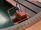
The tractor is to scale and uses all the correct shaped brass metal sections underneath which cannot be seen, it's hinged to the table and rocks if you push down on the decking and flex table. The Vacuum Engine Cover is Tin Plate with brass sections soldered to it, the Drive wheel under the Tractor is made from plastic with a plastic gear attached to the side of it and the piece of rag in the mans hand is paper.
David.
Bit of history.
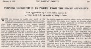
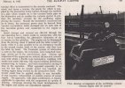
This next drawing is the one I have Modelled.
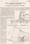
My TURNTABLE is based on the LNER type ( Kings Cross ) but I have put the Vacuum Accumulators above the decking not underneath.
The only way I knew to make something accurate and solid was to build the pit out of STEEL so I did, I weighed the complete TURNTABLE assembly the other day and it weighs 12.6 Kg that's not a Typo that's 27.78 Lbs.
The pit base is made from 10# Black Iron (1/8"thick ) this I Gas Axed out of a square sheet to a dimension slightly larger than needed to allow for the pit wall to sit on and be welded to , immediately the disc dropped I poured cold water around its outer edge this causes the disc to shrink and take on a concave shape. A strip of 10# was cut for the pit wall and a thin strip was cut and curved into a circle for the top lip this supports the Pit on the Base board and is what the Coping and the outer ring of timber walking boards are fixed to.
The welding was all done by Ark there were 12 / 2.5 mm electrodes used in total, the pit wall was tack welded to the disc complete with the Table access service hole then the top lip tacked welded to the wall then fully welded with no distortion within 1mm when cooled. I was able to use any machinery after hours where I worked so long as I put everything back as I found it ready for the boys in the morning, one evening with the aid of the crane I swapped over and put a four jaw 2' chuck onto the 12' MAXSON lathe, I turned the lip and pit wall and machined a flat section on the disc near the base of pit wall for the pit Track Rail to be soldered to and machined out the centre hole, I then reversed the pit on the chuck and machined off a flat section on the underside around the centre hole for the bearing housing to be mounted against and then trimmed the disc edge and machined the underside of the lip.
The Table girder frame is made from 0.012" tin plate with brass sections soldered on to finish it off, the decking is Balsa wood and hand rails are brass. The Code 70 rails are soldered to small pieces of copper clad which are fixed to the cross beams. There is a Collet soldered to the centre section between the main frames which clamps tightly to the hardened main shaft this is hollow for some of its length for the rail wires to be fed through. The 2 Table locking Levers are movable and are made of brass and the Angle Iron slotted guide mounted on the decking is made of four sections all mitred and soldered together, the push levers are brass and also move and can be folded back against the deck or left in any position. The two Vacuum Accumulators are brass with copper ends and soldered together and considering when welding something that becomes sealed when cooled a partial vacuum is created within ( smile ). The concrete dome on the pit base under the centre of the table is Tin Plate soldered in position with the drainage around its edge.
Our State Library had at the time many publications one of which was the Railway Gazette a must to read, I searched the details of the Cowans Sheldon Vacuum Tractor that was patented by them this was first applied to the Kings Cross Turntable in 1933, improvements were made and I have modelled the improved one of 1936. Photo copping was not allowed but the library would Micro Film any page that you listed down for a small fee which took a couple of weeks and they would also print off copies from the film which they did for me.
The tractor is to scale and uses all the correct shaped brass metal sections underneath which cannot be seen, it's hinged to the table and rocks if you push down on the decking and flex table. The Vacuum Engine Cover is Tin Plate with brass sections soldered to it, the Drive wheel under the Tractor is made from plastic with a plastic gear attached to the side of it and the piece of rag in the mans hand is paper.
David.
Bit of history.


This next drawing is the one I have Modelled.

David Waite
Western Thunderer
The mechanism.
The Collet on the Turntable that clamps to the main shaft is accessible by sliding a section of the timber decking to one side which just clears the underside of either Vacuum Accumulator. Screwed to the centre of the underside of the Pit is a Aluminium cast bearing housing this was part of a Testing machine for a laboratory that was discarded, it has Double row ball races at both ends with a space in between, this space is where I have positioned the polarity change over disc for the DC supply to the rails on the Turntable. The disc is copper clad with 4 segments on it and is mounted on a boss, two wiper arms that are attached to a terminal strip rub on the segments, the disc can be turned to any position in relation to the position of the Turntable so the changing over of the polarity doesn't interfere with lining up of Rails. The main shaft continues through the lower bearing for another 35mm and is supported near its end by a 20x3 Aluminium strip I don't think it needs support but it gives piece of mind.
Mounted on the shaft immediately below the lower bearing is a Aluminium Indexing Disc it is 260mm in diameter and 5mm thick, as only have one rail entering the Turntable on either side of the Pit and these are directly opposite each other there are only Two notches required on the Indexing Disc for the Micro Switches these of course are directly opposite each other, there are also Two holes drilled through this Disc for the Locking Pin.
Under the Indexing Disc on the shaft is a small diameter Drive Gear the larger diameter gear is on the out put shaft of the Motor unit.
The Motor unit I used is a MODUTROL MOTOR made by HONEYWELL it was made in 1959 and was replaced by Electronic equipment in 1986 I was part of the work force the did the job and I had the perfect use for it, this is the second heaviest single item that makes up the Turntable assembly at a little over 4.5 Kgs. The MODUTROL unit comprises of a 17Watt 23 volt AC Cap start and run Motor that is inside a Aluminium housing with a precision gear box all submerged in oil, the output shaft revolves at ONE revolution every 12 minutes hence the smaller gear on the Turntable main shaft, this gives the Turntable a speed of ONE total revolution every 2 minutes or ONE minute to turn a Loco.
The turntable stops with accuracy but naturally there is back lash in the Two drive gears so to hold the Turntable accurately in position when stoped a Hardened Ground Pin is driven through the Indexing plate, this pin was originally going to be worked mechanically by a lever but when I decided to work it from number 15 lever on the Lever Frame it needed be motor driven. I made up a servo unit consisting of a combined 12vdc motor and gearbox that I purchased this drives directly onto a friction clutch which drives a shaft mounted on Two ball races in a metal frame, on this shaft is a cam with Two micro Limit switches that stop the shaft from moving past preset positions, this shaft extends through the end bearing to which there is a linkage attached this linkage drives the slotted crank that drives the Locking Pin through the Indexing Disc this pin holds the Turntable within 0.002".
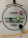
To operate the Turntable. First Move number 15 Lever on the Lever Frame to the Unlocked Position then Push and Hold the Start Button until the Turntable starts to move then release, when it stops put Lever 15 into the Locked Position again.
The entire Turntable is Electrically interlocked there is one micro switch to stop the Turntable via a Notch on the Indexing Disc, the Notch on the opposite side of the Indexing Disc operates another Micro switch which is the proving circuit for the Locking Servo, this prevents the Locking from operating until the hole in the Indexing Disc is directly above the Locking Pin.
The slotted cam that drives the Locking Pin operates Two Micro switches, the first part of its movement turns OFF the MODUTROL MOTOR circuit this is before the Locking Pin enters the hole in the Indexing Disc, the second Micro switch is the proving circuit that lights the "LOCKED LED" on the Control Panel and only when the Locking Pin has passed through the hole.
There is a Third Micro switch above the Indexing Disc and directly above the Locking Pin and is only pushed by the pin in the last 3mm of its travel this closes the circuit for the DC supply to the Rails, so unless the Turntable is locked there is no power to the Rails on the Turntable, there is also a manual switch on the Control Panel to isolate a Loco on the Turntable, a Green indicator LED shows the Rail circuit is ON .
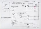
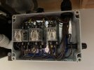
Next to the MODUTROL MOTOR in a plastic Inclosure holds the interlocking relay circuit for the Direction control of the Motor , this circuit is also interlocked with the Servo Locking circuit.
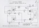
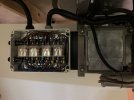
The Servo Locking circuit also has its own Relay interlocking Direction control circuit and is mounted in a plastic inclosure next to the Servo Locking unit.
The MODUTROL MOTOR Circuit.
The MODUTROL MOTOR Relay Inclosure.
The Servo Locking Circuit.
The Servo Relay inclosure.
Turntable Controls.
The Collet on the Turntable that clamps to the main shaft is accessible by sliding a section of the timber decking to one side which just clears the underside of either Vacuum Accumulator. Screwed to the centre of the underside of the Pit is a Aluminium cast bearing housing this was part of a Testing machine for a laboratory that was discarded, it has Double row ball races at both ends with a space in between, this space is where I have positioned the polarity change over disc for the DC supply to the rails on the Turntable. The disc is copper clad with 4 segments on it and is mounted on a boss, two wiper arms that are attached to a terminal strip rub on the segments, the disc can be turned to any position in relation to the position of the Turntable so the changing over of the polarity doesn't interfere with lining up of Rails. The main shaft continues through the lower bearing for another 35mm and is supported near its end by a 20x3 Aluminium strip I don't think it needs support but it gives piece of mind.
Mounted on the shaft immediately below the lower bearing is a Aluminium Indexing Disc it is 260mm in diameter and 5mm thick, as only have one rail entering the Turntable on either side of the Pit and these are directly opposite each other there are only Two notches required on the Indexing Disc for the Micro Switches these of course are directly opposite each other, there are also Two holes drilled through this Disc for the Locking Pin.
Under the Indexing Disc on the shaft is a small diameter Drive Gear the larger diameter gear is on the out put shaft of the Motor unit.
The Motor unit I used is a MODUTROL MOTOR made by HONEYWELL it was made in 1959 and was replaced by Electronic equipment in 1986 I was part of the work force the did the job and I had the perfect use for it, this is the second heaviest single item that makes up the Turntable assembly at a little over 4.5 Kgs. The MODUTROL unit comprises of a 17Watt 23 volt AC Cap start and run Motor that is inside a Aluminium housing with a precision gear box all submerged in oil, the output shaft revolves at ONE revolution every 12 minutes hence the smaller gear on the Turntable main shaft, this gives the Turntable a speed of ONE total revolution every 2 minutes or ONE minute to turn a Loco.
The turntable stops with accuracy but naturally there is back lash in the Two drive gears so to hold the Turntable accurately in position when stoped a Hardened Ground Pin is driven through the Indexing plate, this pin was originally going to be worked mechanically by a lever but when I decided to work it from number 15 lever on the Lever Frame it needed be motor driven. I made up a servo unit consisting of a combined 12vdc motor and gearbox that I purchased this drives directly onto a friction clutch which drives a shaft mounted on Two ball races in a metal frame, on this shaft is a cam with Two micro Limit switches that stop the shaft from moving past preset positions, this shaft extends through the end bearing to which there is a linkage attached this linkage drives the slotted crank that drives the Locking Pin through the Indexing Disc this pin holds the Turntable within 0.002".
To operate the Turntable. First Move number 15 Lever on the Lever Frame to the Unlocked Position then Push and Hold the Start Button until the Turntable starts to move then release, when it stops put Lever 15 into the Locked Position again.
The entire Turntable is Electrically interlocked there is one micro switch to stop the Turntable via a Notch on the Indexing Disc, the Notch on the opposite side of the Indexing Disc operates another Micro switch which is the proving circuit for the Locking Servo, this prevents the Locking from operating until the hole in the Indexing Disc is directly above the Locking Pin.
The slotted cam that drives the Locking Pin operates Two Micro switches, the first part of its movement turns OFF the MODUTROL MOTOR circuit this is before the Locking Pin enters the hole in the Indexing Disc, the second Micro switch is the proving circuit that lights the "LOCKED LED" on the Control Panel and only when the Locking Pin has passed through the hole.
There is a Third Micro switch above the Indexing Disc and directly above the Locking Pin and is only pushed by the pin in the last 3mm of its travel this closes the circuit for the DC supply to the Rails, so unless the Turntable is locked there is no power to the Rails on the Turntable, there is also a manual switch on the Control Panel to isolate a Loco on the Turntable, a Green indicator LED shows the Rail circuit is ON .
Next to the MODUTROL MOTOR in a plastic Inclosure holds the interlocking relay circuit for the Direction control of the Motor , this circuit is also interlocked with the Servo Locking circuit.
The Servo Locking circuit also has its own Relay interlocking Direction control circuit and is mounted in a plastic inclosure next to the Servo Locking unit.
The MODUTROL MOTOR Circuit.

The MODUTROL MOTOR Relay Inclosure.

The Servo Locking Circuit.

The Servo Relay inclosure.

Turntable Controls.

David Waite
Western Thunderer
Hi paratomA fantastic lever frame. I have been thinking of building one myself based on the Midland Railway design and a similar size. Were any of your parts laser cut for you and how did you do the arms, were they cast or cut on a pantograph miller?
Nothing Laser Cut or Cast mainly done by hand some turning and some Milling.
The Levers were just cut on a guillotine one by one and ends trimmed with Gilbow Tin snips the handles were turned then slotted by hand and 45% Silver Soldered together.
David.
David Waite
Western Thunderer
This slightly blurred photo (sorry) is the Servo frame being built its Limit stop Cam and the drive shaft can be seen in the background this shaft runs through the bearings that can be seen. The flat piece of metal is where the Two Micro switches will be mounted, these Micro switches stop the Servo at the end of its stroke in both directions.
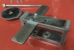
The completed assembly the large brass gear is the Friction Clutch. The reason I fitted this clutch is because that little 12Volt motor and gearbox has a 10 Kg force and if something ever become jammed its nice to know the clutch will slip and no damage can be done.
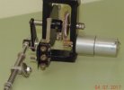
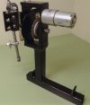
Here is the Servo in position with its operating rod attached to the Slotted Crank. This position shows the Turntable ready to revolve the Locking Pin is Down and out of the Indexing Disc and the Slotted Crank is pushing against the Micro switch closing the control circuit for the MODUTROL MOTOR.
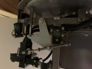
This shows the Turntable in the Locked position with the Locking Pin through the Indexing Disc, the Slotted Crank is now pushing on the Locked Proving Micro switch. The Micro switch controlling the MODUTROL MOTOR control circuit is now open.
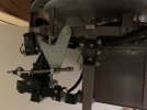
This view is looking at the Cast Bearing housing screwed to the underside of the Pit, the Polarity change over disc can be seen on the Main shaft, the Micro switch in the distance closes the DC circuit to the Rails on the Turntable when the Locking Pin is through the Indexing Disc and at the end of its Stroke. The hole in the Indexing Disc can be seen to the left of the photo and the Indexing notch on the outer edge can be seen on the right. The flat curved Strip of metal running around the support frame is for mounting the Indexing Micro switches at any position depending on where the track work is placed.
In this view can also be seen the Concave shape of the Pit.
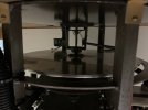
Overall view showing the Indexing Micro switch ( Two Brown wires ) and yes the MODUTROL MOTOR is upside down, and I made a typo earlier its 24VAC not 23 sorry , if you are wondering what the distance is from the base board to the square shaft under it that length is 318mm
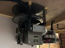
Opposite Side View. The Micro switch on the Left hand side is the Indexing Proving Micro switch for the
Servo Locking circuit.
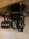
A view looking up.
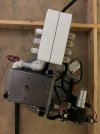

The completed assembly the large brass gear is the Friction Clutch. The reason I fitted this clutch is because that little 12Volt motor and gearbox has a 10 Kg force and if something ever become jammed its nice to know the clutch will slip and no damage can be done.


Here is the Servo in position with its operating rod attached to the Slotted Crank. This position shows the Turntable ready to revolve the Locking Pin is Down and out of the Indexing Disc and the Slotted Crank is pushing against the Micro switch closing the control circuit for the MODUTROL MOTOR.

This shows the Turntable in the Locked position with the Locking Pin through the Indexing Disc, the Slotted Crank is now pushing on the Locked Proving Micro switch. The Micro switch controlling the MODUTROL MOTOR control circuit is now open.

This view is looking at the Cast Bearing housing screwed to the underside of the Pit, the Polarity change over disc can be seen on the Main shaft, the Micro switch in the distance closes the DC circuit to the Rails on the Turntable when the Locking Pin is through the Indexing Disc and at the end of its Stroke. The hole in the Indexing Disc can be seen to the left of the photo and the Indexing notch on the outer edge can be seen on the right. The flat curved Strip of metal running around the support frame is for mounting the Indexing Micro switches at any position depending on where the track work is placed.
In this view can also be seen the Concave shape of the Pit.

Overall view showing the Indexing Micro switch ( Two Brown wires ) and yes the MODUTROL MOTOR is upside down, and I made a typo earlier its 24VAC not 23 sorry , if you are wondering what the distance is from the base board to the square shaft under it that length is 318mm

Opposite Side View. The Micro switch on the Left hand side is the Indexing Proving Micro switch for the
Servo Locking circuit.

A view looking up.

Graeme Lewis
Member
DavidThis slightly blurred photo (sorry) is the Servo frame being built its Limit stop Cam and the drive shaft can be seen in the background this shaft runs through the bearings that can be seen. The flat piece of metal is where the Two Micro switches will be mounted, these Micro switches stop the Servo at the end of its stroke in both directions.
View attachment 179928
The completed assembly the large brass gear is the Friction Clutch. The reason I fitted this clutch is because that little 12Volt motor and gearbox has a 10 Kg force and if something ever become jammed its nice to know the clutch will slip and no damage can be done.
View attachment 179930
View attachment 179931
Here is the Servo in position with its operating rod attached to the Slotted Crank. This position shows the Turntable ready to revolve the Locking Pin is Down and out of the Indexing Disc and the Slotted Crank is pushing against the Micro switch closing the control circuit for the MODUTROL MOTOR.
View attachment 179932
This shows the Turntable in the Locked position with the Locking Pin through the Indexing Disc, the Slotted Crank is now pushing on the Locked Proving Micro switch. The Micro switch controlling the MODUTROL MOTOR control circuit is now open.
View attachment 179934
This view is looking at the Cast Bearing housing screwed to the underside of the Pit, the Polarity change over disc can be seen on the Main shaft, the Micro switch in the distance closes the DC circuit to the Rails on the Turntable when the Locking Pin is through the Indexing Disc and at the end of its Stroke. The hole in the Indexing Disc can be seen to the left of the photo and the Indexing notch on the outer edge can be seen on the right. The flat curved Strip of metal running around the support frame is for mounting the Indexing Micro switches at any position depending on where the track work is placed.
In this view can also be seen the Concave shape of the Pit.
View attachment 179936
Overall view showing the Indexing Micro switch ( Two Brown wires ) and yes the MODUTROL MOTOR is upside down, and I made a typo earlier its 24VAC not 23 sorry , if you are wondering what the distance is from the base board to the square shaft under it that length is 318mm
View attachment 179938
Opposite Side View. The Micro switch on the Left hand side is the Indexing Proving Micro switch for the
Servo Locking circuit.
View attachment 179940
A view looking up.
View attachment 179942
Goodness me - words fail me. Amazing.
Regards, G
David Waite
Western Thunderer
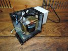
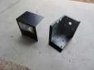
The Power supply to run the MODUTROL MOTOR is from the original 100W 24v AC Transformer , of course this not the original one from 1959 it was obviously replaced at some point in time, there were originally Two Step controllers it supplied power to and also their control circuit so it is probably a little over size now just for one, the next photos show the transformer and a metal enclosure I made with a Mains switch and indicator lamp. This is mounted upside down under the base board so the top of the casing in the photo is actually the base hence the drilled heat holes on the side panel near the work bench are in fact at the top.
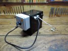
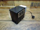
The earth lead with the Spade terminal hanging loose connects to the vented cover.
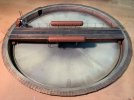
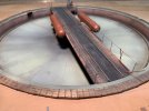
The Turntable.
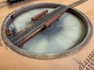
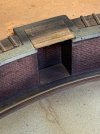
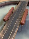
The Vacuum Motor Cover is made from Tinplate with Brass fittings I made representing the various parts.
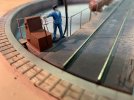
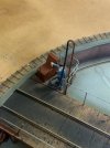


The earth lead with the Spade terminal hanging loose connects to the vented cover.


The Turntable.


The Vacuum Motor Cover is made from Tinplate with Brass fittings I made representing the various parts.


BLOCK INSTRUMENTS
David Waite
Western Thunderer
In 1996 I built by hand and finished and installed 6 fully working BLOCK INSTRUMENTS [ 3 pairs ] they are based on the WINTERS BLOCK Single Wire Two Position DOUBLE LINE INSTRUMENTS.
History
Siemens Bros LTD were the builders of the Block Instruments that were patented by George Kift WINTER of the Madras Railway Company [INDIA] in 1880.
Fifty of these were originally purchased by the Victorian Railways [VR] in 1883 however they found faults with the original design which were caused by the timber warping that the mechanism was mounted on so Brass castings were made along with other alterations to improve their operation, from the original Two Coil Instrument to Three coil in 1888, the Commutator was also removed from the side of the Instrument and placed on the Centre front. The original Instruments were for Single Line use VR modified the design for them to become DOUBLE LINE Instruments these lasted in operation on the North East Broad Gauge Main Line up to a couple of years before I retired I think it might have been around 2019 or 2018 it was the Copper wire theft from the telegraph poles that finally put them out of action after around 130 years of operation.
The Instruments only use Power when being used so battery life is long when I started with the rail they were run by one 6VDC BIG JIM or EVEREADY Dolphin battery, towards the end they were run from the mains supply with a globe in series for short circuit protection.
The 6 Instruments I made are Two Coil Double Line Block Instruments they each stand 17" tall they work as the Prototype dose, they can also control Starting Signals if I wish to do so, my wife helped me to wind all 24 coils of fine Enamel Copper wire which is certainly a job for two people. They look nothing like the Winters Instruments they are of my own design, the First reason for this is I don't have the space on the Block shelf at Pine Oak Junction so the UP & DOWN needles on each Instrument needed to be one above the other not side by side all the UP LINE Needles are at the top of each Instrument the DOWN LINE Needles are underneath, the Commutator for each has a brass plate with UP or DOWN stamped on it so you know which needle it is for in any case the UPPER needle UP LINE , LOWER needle DOWN LINE simple. The second reason for their design is I wanted something that looked a bit British and the WINTERS dose not in my book. The casings are made from pine and have weathered the last 27 years of vast temperature changes very well, it is 38C out side at the moment and a nice 29C in the attic as I type this come winter it will drop to 10C or less. Each Pair of Instruments has a matching Bell sound from LOW , MEDIUM to HIGH the High sounding Bells being CHIMTONSTOKE to PINE OAK Junction , Medium sounding Bells being PINE OAK junction to COALCHESTER , and Low sounding Bells from PINE OAK Junction to BRIDGETON.
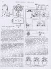
This is a scan I did from my book of POWER RAILWAY SIGNALLING by RAYNAR WILSON printed I believe 1909
it shows the original Patent with the Commutator Handle on the left hand side .
This Photo I took at Kilmore East showing the Instruments in their final design they were in full daily working order shown here about 10 years ago. The grey box on the wall next to number one Lever that has a power lead plugged into it is the power supply for the BLOCK Instruments.
As can be seen the Commutator handle is in the front above the Tapper Key and between the two Needles.
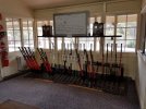
History
Siemens Bros LTD were the builders of the Block Instruments that were patented by George Kift WINTER of the Madras Railway Company [INDIA] in 1880.
Fifty of these were originally purchased by the Victorian Railways [VR] in 1883 however they found faults with the original design which were caused by the timber warping that the mechanism was mounted on so Brass castings were made along with other alterations to improve their operation, from the original Two Coil Instrument to Three coil in 1888, the Commutator was also removed from the side of the Instrument and placed on the Centre front. The original Instruments were for Single Line use VR modified the design for them to become DOUBLE LINE Instruments these lasted in operation on the North East Broad Gauge Main Line up to a couple of years before I retired I think it might have been around 2019 or 2018 it was the Copper wire theft from the telegraph poles that finally put them out of action after around 130 years of operation.
The Instruments only use Power when being used so battery life is long when I started with the rail they were run by one 6VDC BIG JIM or EVEREADY Dolphin battery, towards the end they were run from the mains supply with a globe in series for short circuit protection.
The 6 Instruments I made are Two Coil Double Line Block Instruments they each stand 17" tall they work as the Prototype dose, they can also control Starting Signals if I wish to do so, my wife helped me to wind all 24 coils of fine Enamel Copper wire which is certainly a job for two people. They look nothing like the Winters Instruments they are of my own design, the First reason for this is I don't have the space on the Block shelf at Pine Oak Junction so the UP & DOWN needles on each Instrument needed to be one above the other not side by side all the UP LINE Needles are at the top of each Instrument the DOWN LINE Needles are underneath, the Commutator for each has a brass plate with UP or DOWN stamped on it so you know which needle it is for in any case the UPPER needle UP LINE , LOWER needle DOWN LINE simple. The second reason for their design is I wanted something that looked a bit British and the WINTERS dose not in my book. The casings are made from pine and have weathered the last 27 years of vast temperature changes very well, it is 38C out side at the moment and a nice 29C in the attic as I type this come winter it will drop to 10C or less. Each Pair of Instruments has a matching Bell sound from LOW , MEDIUM to HIGH the High sounding Bells being CHIMTONSTOKE to PINE OAK Junction , Medium sounding Bells being PINE OAK junction to COALCHESTER , and Low sounding Bells from PINE OAK Junction to BRIDGETON.
This is a scan I did from my book of POWER RAILWAY SIGNALLING by RAYNAR WILSON printed I believe 1909
it shows the original Patent with the Commutator Handle on the left hand side .

This Photo I took at Kilmore East showing the Instruments in their final design they were in full daily working order shown here about 10 years ago. The grey box on the wall next to number one Lever that has a power lead plugged into it is the power supply for the BLOCK Instruments.
As can be seen the Commutator handle is in the front above the Tapper Key and between the two Needles.

David Waite
Western Thunderer
Hi Dog Star thank you for your comment I much appreciate it.This is a most informative and eductional post although - being honest - I think that the subject is a bit beyond my ken. That you have contributed the subject to WT is to be applauded for broadening our knowledge, thank you.
I am not really sure what I should post on WT that will be of value to the members as this is all new to me in fact this is the first time in my life I've ever operated a computer so its a very big and scary time worrying not to do the wrong thing. I'm trying to keep my wording as short as I can without missing out on important stuff that could leave holes in the descriptions. Ive always liked a bit of history about whatever to give a basis of what or how the subject came about this is the reason for my ramblings.
David.
michael mott
Western Thunderer
David you could have fooled me! reading through your posts I would have thought that you were an old hand at computers, The clean and tidy work of all the electrical/mechanical stuff to operate your layout and the drawing of it in the first post gave the impression that you have been at it for years. I also agree with Dog Star regarding the info in your previous post.this is the first time in my life I've ever operated a computer
Michael
David Waite
Western Thunderer
This photo is at CHIMTONSTOKE terminus, the terminus station will be eventually built on the base board that can be seen to the lower right.
This Block Instrument works to PINE OAK Junction, the items on the wall far right are as follows this is a Knife switch which isolates two Generator Station Service Phones from the main party line, one which can be seen here. The small Black Bakelite box is a Lightning arrestor, the timber box next left holds the battery for the phone.
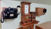
PINE OAK JUNCTION , Due to the lighting and reflections it was hard to get a clear photo the colours are not correct its the best I could do.
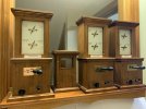
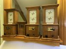
Colours are better in this older photo the Lever Frame shown will be part of PINE OAK JUNCTION signal box
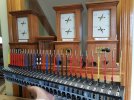
In the distance are the Block Instruments for BRIDGETON left and COALCHESTER right both mounted together for convenience,
these stations won't be modelled the Block Instruments just represent their Signal boxes.
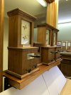
BRIDGETON left COALCHESTER right
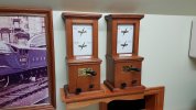
This Block Instrument works to PINE OAK Junction, the items on the wall far right are as follows this is a Knife switch which isolates two Generator Station Service Phones from the main party line, one which can be seen here. The small Black Bakelite box is a Lightning arrestor, the timber box next left holds the battery for the phone.

PINE OAK JUNCTION , Due to the lighting and reflections it was hard to get a clear photo the colours are not correct its the best I could do.


Colours are better in this older photo the Lever Frame shown will be part of PINE OAK JUNCTION signal box

In the distance are the Block Instruments for BRIDGETON left and COALCHESTER right both mounted together for convenience,
these stations won't be modelled the Block Instruments just represent their Signal boxes.

BRIDGETON left COALCHESTER right

David Waite
Western Thunderer
Hi MichaelDavid you could have fooled me! reading through your posts I would have thought that you were an old hand at computers, The clean and tidy work of all the electrical/mechanical stuff to operate your layout and the drawing of it in the first post gave the impression that you have been at it for years. I also agree with Dog Star regarding the info in your previous post.
Michael
Western Thunder is the first and only time I've ever operated a computer by myself, I draw everything by hand and always have I applaud people when I read what they do and make with their computers its amazing but not me I'm just very pleased to be able to operate my new computer and be part of WT.
David
Threadmarks
View all 19 threadmarks
Reader mode
Reader mode
