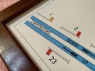
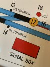
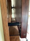
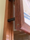
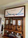
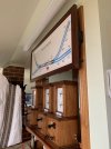
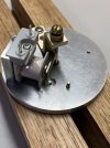
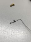
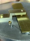
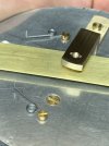
Well this new thread title above says it all,
At the start of this year I up dated my glasses, I had new lenses made complete with new frames but by mid May I could not clean the
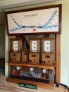
misty haze off the new left lens no mater what I used, however it wasn't a grubby lens a trip to a Ophthalmologist confirmed I had lost vision in my left eye, apparently my eye is working as good as the other but the jelly like substance that makes up the eyes inside has failed and cannot be repaired so every thing I see through my left eye now is blurred, But I'm not giving up I have repaired and built things all my working life its what I'm all about, it was once my job that I earn't a living from and now I put my skills to home maintenance and my hobby I'm lost without tools they are my life. So since mid May I kept out of the shed and concentrated on doing day to day things like walking up steps without tripping forward and general maintenance things around the house that didn't require good vision to do and of course learning to accept what has happened this I can say I have done, I have accepted it as one must, WT has been a important link to my hobby its been a struggle to find and post photos but it has been a driving force more than you could imagine.
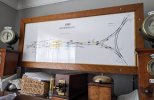
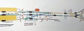
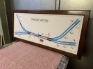
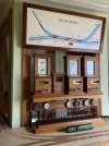
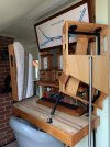
Two weeks ago when I decided to have ago at making the spacers for the rear of the Diagram Frame was the first time I had gone into the shed to make anything since May, working the lathe was second nature no problem I'm so glad the dials are metric and imperial I was bought up on IMP and they are so much easer to work and see which is important to me now, each IMP division is a thou the metric divisions are .003 / .002 and .015 on the metric scales on the Lathe and Mill so simplicity is the key, I fitted a RDO on the mill sometime ago so I don't have to look at the hand scales anymore other than the down feed, the biggest problem I found was lighting I need to put extra movable lamps on the equipment.
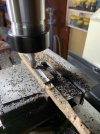
I found I have to get so close to the job now safety has become a concern in fact I had to remove a handle off the mill so I could get my head in closer to see what the cutter was doing with my glasses and magnifier head piece on its about 4" from the cutter to see clearly.
Am I making anything, yes I am so pleased to say, I have a few jobs on the go, One, is to modify and improve my dust extractor so I can make the Timber casings for the 3 repeaters that I have made, which are still sitting in a box. Two, is the making of metal oval Number plates to indicate which signal each Sykes repeater refers to. The final item was a spur of the moment thing about a week and a half ago I was watching a IRSE video about Stick relays that were mounted to the rear of block instruments and their operation, the chap had everything working for the demonstration including two Repeaters one was a RE THOMPSON Track Circuit Indicator, seeing it working I thought I know how to make that but will I be able to and at what average of build quality. Well I have started and I'm doing pretty good considering, I have made mistakes not judging distances and clipping the cutter on the job all eye sight related problems which has made me take a step back and rethink my movements anyhow,
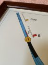
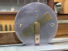
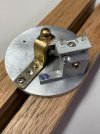
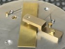
Here is my, RE THOMPSON GWR TRACK CIRCUIT INDICATOR / INSTRUMENT NUMBER 10.
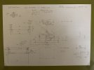
Trying to scale up and draw this sketch from photos took me days my right eye gets very tired after a short time, I know there will be many if not all dimensions not to scale with each other but as long as the overall finished item looks convincing I will be more than happy,
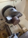
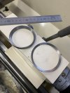
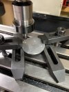
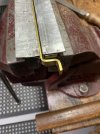
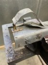
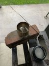
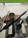
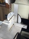
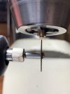
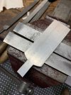
The Face plate is 4.6mm thick Aluminium, the hole saw seen here is 75 mm Dia.
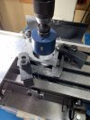
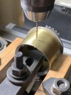
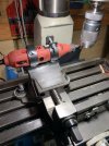
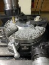
To bring the diameter down to the required size I used the rotary table the sections un cut under the clamps I filed down by hand.
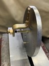
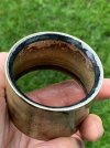
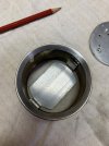
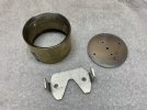
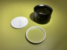
The outside Diameter of the instrument casing is 70 mm with 1mm wall thickness so this disc is a little under 67 mm .
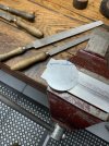
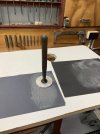
I lapped the surface using this old valve grinding tool that belonged to my father the suction cup has been replaced many times by me but the handle is original from the 1930s .
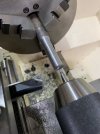
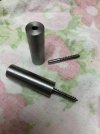
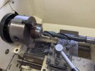
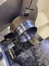
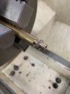
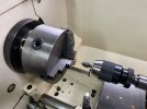
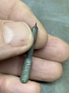
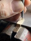
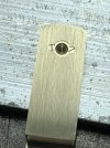
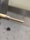
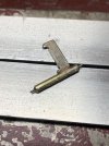
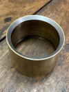
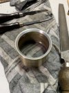
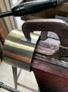
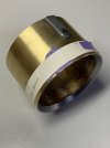
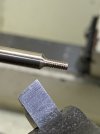
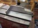
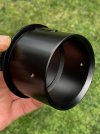
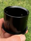
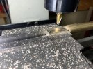
This is the start of the front bearing its the second attempt I ruined the first.
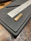
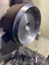
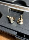
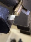
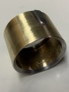
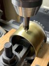
I used 1200 W&D to remove the cutter marks, the fine marks left by the machining on the original instruments change directions
on the bearing face, the bearing end which is the highest has the machining lines running lengthways with the bearing the lower
mounting section has the machining marks cross ways I've tried to do the same.
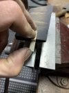
The second attempt lived.
