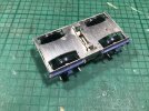
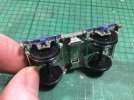
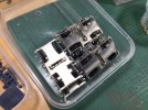
4mm On Heather's workbench - on a Holden to…Yarmouth?

simond

Western Thunderer
Thanks Dave, I’d have done the same,

indeed, at work, I try to ensure that groups of parts and assemblies contain a word that doesn’t appear elsewhere - our latest instruments are the “Pro 2” series, and it makes searching the parts database so much easier. Combining it with the “group code” (eg “machined parts”) saves a bit of time.

Happily, in this case, I did use a suitably rare word, and spelled it correctly!

The trouble starts when there’s more than one logical answer. In this case the commode handle tool was not in the drawer marked “jigs”, but appeared in the cigar tin marked coaches…. It’s going back in the right drawer!
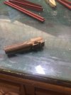
image.jpg

the tail of the bent wire is inserted in the hole, the wire is pulled tautly around the “carefully machined former” (AKA the sticky-outy-lump) and then bent sharply down into the slot using thin-nose pliers to make the corner tight.
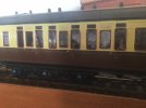
image.jpg

it does appear that the middle one is not quite as nice as the far one, but from a coach-length away, you’d be hard pressed to tell.

atb
Simon
 

GrahamMc

Western Thunderer
The trouble starts when there’s more than one logical answer. In this case the commode handle tool was not in the drawer marked “jigs”, but appeared in the cigar tin marked coaches…. It’s going back in the right drawer!
Handy little jig, perhaps this post could go somewhere where it might be more easily found? :)
 

GrahamMc

Western Thunderer
Why not simply download the post and save it, with a descriptive filename, on your computer?
Dave
True enough Dave but I wasn't thinking of myself. I was thinking it would be of use to others. I realise that if you do a search for something like commode handles it will come up but with the wealth of knowledge and experience available on WT I find the occasional browse through the Techniques section will always come up with something interesting. Sometimes putting things there can make ideas that bit more accessible.
It was also a bit of a joke on Simond's comment about putting things in the right drawer/place making things easy to find.....OK......not a very good joke.....:oops:
 
Last edited:

OzzyO

Western Thunderer
I know a lot of modellers really dislike building coaches. I can understand why. There’s so much fiddly and repetitive work, often on a single vehicle. Multiply that by however many coaches I’m working on, and you have to wonder about my sanity at taking on such tasks!

Having satisfied myself the bogies could be fitted to the floors without too much pain, I thought it might make sense to review all the partly-built coaches. So far, I’ve been assembling new kits, but there was a whole box full of floors, sides and ends that had been mostly stuck together some time ago.

I hauled everything out, identified which diagrams were which, and made sure I had enough parts to make whole coaches. Being charitable, the previous builder hadn't done a completely marvellous job. My guess is a low wattage iron was deployed, and flux residues hadn’t been cleaned off or neutralised. Slowly, I worked through everything, repairing and replacing missing hinges, drop lights, and end details as required. Tedious stuff.

With all that done, I started looking at other details that would need attention. The commode handles are relatively simple affairs, but will probably need a jig to form to shape reliably. Likewise for the end handrails. Then I realised the brake thirds had loads of handrails. Each double luggage door pair had a pair of straight grab handles - another jig might be sensible. There were also long grab rails along the sides, although the kit hadn’t been designed with etched holes for such fripperies.

I checked photos, and sure enough the long rails survived through to scrapping. From a drawing it was simple to transpose the locations to the sides.

View attachment 169049

The question was, though, how to drill holes centred reliably on the beading. The answer was it couldn’t be done. Pragmatically, I decided to drill against the beading and into the central panels instead. I doubt the subterfuge will be noticeable at this scale.

View attachment 169050

With however many holes marked out and drilled 0.45mm diameter, plus those double-door grab rails, I set to with pliers and made the long rails. I’ve decided commode rails and other sundries will be left until the models are painted, but the long rails really needed to be soldered in place for strength. First attempts at bending were rubbish, so I laid down tools and walked away from the bench. Next morning, the bending-fu was working, as this photo shows.

View attachment 169051

This was about halfway through. The plastic tub contains the last ends that needed detailing. I’m pleased to say all the handrails are now made. My sanity is still teetering on the brink, but I’m not entirely sure it’s down to building these coaches.

Next week, I’ll get back to more bogies, I think. I keep jumping round between tasks to try and alleviate the tedium a little. Favourite music played loud also helps.

Heather,

I do understand why you have done it, but it may have been better to have drilled the holes below the beading on the coach. As having the handrails fixed above the beading will be more viewable as most models are viewed from above.
Or you could have made a jig to help drill the holes in the correct place.

The build is staring to come together,

OzzyO.
 

Heather Kay

Western Thunderer
it may have been better to have drilled the holes below the beading on the coach

I did consider this. However, the handrails on the real thing are mounted on the bead, but appear to be kinked upwards slightly. I felt above the bead was a reasonable compromise - especially at this scale.

To explain some of the decisions around this build - like no internal detail beyond the provided compartment dividers, choices of coupling, etc - the client will use these coaches running along a mainline towards the rear of his layout. His main focus is goods stock, and his layout is focused on goods operation. The passenger trains will be essentially set dressing.
 

Heather Kay

Western Thunderer
Hello. Been a while. Lots of non-modelling stuff been happening, getting in the way of bench time. I have been slowly plodding on with the endless bogie builds, and trying to work out some way of making simple jigs to aid bodywork construction.

Other news is that fantastic progress has been made on sourcing detailing for the bogies. More info on that in due course, but it is all very exciting.

Back to the soldering iron.
 
Adventures in three dimensions

Heather Kay

Western Thunderer
I guess it’s time for a sit-rep.

Things have been chugging along here, but I’m afraid Mrs Mojo wandered off. A horrid cold made a nuisance of itself for a week or two, and other domestic nonsense kept getting in the way.

Back in October, I received a small box from the Basingstoke area. In it was the first prototypes for bogie detailing. Having struggled to find any suitable springs or axleboxes from the trade, it had been suggested that Peter Beare, aka @Spike of this parish, might be able to help with his newfangled 3D print gadget. After some discussion, I prepped some 2D scale drawings of the required parts and sent them on.

At this point it’s worth mentioning that the client and I had come to a realisation that the GER coaches under construction didn’t actually run on the Fox pattern bogies that had been acquired for the job. It was agreed this was a slightly silly error to have made, but things had progressed so far along the wrong route it really wasn’t worth attempting to change tack. At 4mm scale, the differences will not really be noticeable once all the various step boards and a layer of filth have been applied.

322A00F0-41D7-4ED9-AEE5-7C95168576D6.jpeg

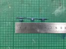
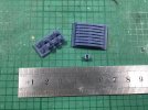
These are the various parts that arrived in the box from Basingstoke. The axlebox and spring were printed separately, for various logistical reasons. The spring has a square peg that sits in a square slot in the top of the axlebox. On the right you can see the front and back of an assembled set. The rear of the axlebox has a slot intended to allow the wheel bearing cup to slide up and down. The ends of each spring had a dimple for me to drill out a hole to accept the Rumney kit parts for the dampers.

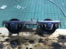
Anyway, the box contents were hurriedly assembled on a pair of bogies. When I say "hurriedly" I mean the evening before the morning we were to set off for Somerset. Burning the midnight oil - well, nearly - resulted in a pair of bogies mostly like this:

565A3FEB-1541-4349-B81F-EBB11489232E.jpeg

To say I was tickled pink would be fair. Now, there were issues. Peter had reproduced my drawing perfectly, but I hadn’t thought things through. First, the leaf springs were to scale depth. This meant they stood off from the bogie side frame like the real ones do. The only points for fixing them in place were the square slot and the axlebox itself - and that was cyanoacrylate fixing the resin to nickel silver. Not exactly ideal because the small slot, while allowing the bearing cup to move up and down adequately for riding bumps, an excessive movement could ping the box off. I had quite a bit of breakage drilling out the ends of the springs, too, and the springs needed to be a gnat's crotchet longer overall. (The shoddy wire work was tidied after this image was taken.)

After a very productive meeting with the Beare Clan at the ScaleSeven Mark meeting in Somerset, Peter went away and has reworked things.

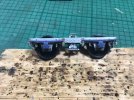
E8CD13D0-565C-49A4-BBE3-C370B9A1EF06.jpeg

We decided the bearing slot may as well be open to the bottom of the box. This allows the axle full travel up and down, and ought to prevent the accidental pinging mentioned earlier. The springs have been widened so they contact the bogie frame, and they have been stretched by half a millimetre at each end. Peter has also managed to print the hole for the damper wire - or should that be not print the hole!

Again, I am tickled pink with the results. I’m just about to try fitting the new prints. If it looks good, which I suspect it will, I’ll get the full set ordered from the Basingstoke Printworks.

Meanwhile, Best Beloved and I spent a weekend away playing plastic planes up in Shropshire at the IPMS Scale Model World exhibition. As it happens, the client lives near Oswestry and foolishly offered us bed and board for a few days. Being able to spend time in comfy surroundings with excellent grub meant we could discuss the various coaching requirements. With some further research, it turns out these coaches most likely had electric lighting as built. This is useful because we haven’t been able to find out how gas lighting was installed - even the luminaries of the GER Society couldn’t help!

So, that’s where we are. As I type, I have three more pairs of bogies to put together. Now we have suitable details for the running gear, I feel happier. Then I shall start working up the underframe details, and eventually work out jigs to aid body assembly and handrail forming. This build will slowly grind into motion again.
 

Mike Garwood

Western Thunderer
I've built a few of these, including the brilliant bogies for the BR mk 1 coaching stock. How did you set the ride height? If you don't mind me asking. I have my own method - which is a bit Heath Robinson.

Mike
 

Heather Kay

Western Thunderer
How did you set the ride height?

The honest answer is I’ve not really thought about it properly. Currently, all the bogies are exactly the same and, obviously, will ride at the same height. After I’d built the first pair, I fitted them to a chassis and played around with some weight to get the bearing cups to sort of sit where it looked about right compared to photos of the real thing. I think I settled on 100 grammes or so of extra weight, but I’ll do some more scientific calculation when things have advanced a bit further with construction.

For the axle and bolster springs I’ve used the same steel guitar string - Ernie Ball Custom Gauge 9. I haven’t seen a need to use a stronger wire in the bolsters.
 
Thinking about underframes

Heather Kay

Western Thunderer
Pending the arrival of bogie detail parts - currently stranded in the snow somewhere between Basingstoke and here, I expect - my thoughts turn to the rest of the underframe detailing.

A feature if these carriages was pipe runs along the solebars below each full length footboard. In later years, this feature was on both sides. This is because the air-braked carriages were gradually converted to vacuum braking, and the steam heating went one side while the vac went the other. Logically, the steam pipework must run along the compartment side on all vehicles. So that’s that decided. Logic has little to do with GER carriage building, however. I will stick with my initial assessment, though.

The next job is to work out which way round the bodies were generally orientated on the underframes. Since it has been decided the models are all electrically lighted, the need to find out what sort of gas storage installations were fitted doesn’t matter any more. From my experience, most railway companies constructed their carriages to some kind of pattern. You’d find dynamos under lavatory ends, cell boxes along one side or grouped both sides at one end, that sort of thing. I started reviewing the research material to find the pattern.

What I found was the Great Eastern Railway didn’t have any truck with standardised installations!

I have three diagrams under construction. The kit standard underframe dictates where the dynamo is fitted, and has guidelines indicating cell box locations. This should be easy, right? Well, according to my photo survey earlier, placement of cell boxes varied within a diagram, presumably depending on the lots and when they were built! To pin down which layout went under which carriage will need me to cross-reference running numbers with build dates, and that assumes I can find photos from different lots of each diagram.

I rather think I shall be recommending to the client he lets me choose a "typical" layout for each diagram, with a few variations on a theme to spice things up a bit. I doubt very much anyone would be able to question my choices.

Meanwhile, I found a photo that showed how gas storage was done under a first class carriage. The vehicle had been withdrawn from service in 1959, awaiting scrapping at Stratford, and still had gas lighting. There were paired cylinders, each pair adjacent to a bogie and fitted transversely. The cylinders also appeared to have dished ends. This matches typical catering vehicle layouts, but one standard passenger carriage doesn’t prove anything.

Academic now, anyway, as we are building electrically lit coaches, as built by Stratford in the 1910s and '20s.

So, that’s my morning spent. I still don’t really have a clue! :confused::))
 

Daddyman

Western Thunderer
Exactly the same with ex-NER carriages, Heather - little by way of standardisation, with no rhyme or reason as to which side solebar the vac pipes run along, and stand pipes at the ends that incline both left and right off the vertical, regardless of which side the solebar pipe is on.

Gas lighting in 1959 is no surprise (the LMS were still building gas-lit carriages in the 1930s), but I'm surprised to hear of a carriage with so many gas cylinders. The NER went from 4 tanks to 1 after changing from inefficient gas burners to vastly more efficient incandescent gas burners. I'd be surprised if the GER didn't make the same shift, as the savings in gas were enormous.
 
Top