4mm On Heather's workbench - on a Holden to…Yarmouth?

A journey begins

Heather Kay

Western Thunderer
I do try, but sometimes a thread title doesn’t work on the first go. I’ll think on it.

It started with a phone call. A chap called and asked if I’d be interested in helping him by building some coaches. Well, as it’s more or less what I do these days, I said I was happy to chat about it further. I do try to take notes when chatting on the phone, but it made much more sense for him to email me with more details. I prefer email as it’s easier to keep a digital paper trail of correspondence.

The project sounded interesting. As we were going to be in Shropshire attending a modelling exhibition of some flavour, we arranged that we might pay a visit to give everything a proper looking at. We arrived one morning, were ushered into the rather grand house, and diverted into the dining room. The not insubstantial table was covered in lots of bits of Great Eastern Railway brass coach kits, all neatly laid out for inspection.

The upshot of it all was the client had acquired a selection of part-built models from a good friend who had died a few years before. The client wasn’t happy building coaches, being much more interested in goods stock and operation. He was building a P4 layout set around the London area modelling LNER in 1928, and wanted to have the coaches completed so he could run them in the fashion of passing trains while the fun part of shunting was going on in the foreground. He also wanted to have them finished as a tribute to commemorate his late friend.

Well, I looked at the parts, we chatted about what was wanted, and it all looked fairly straightforward. We agreed an estimated price per coach to complete to a certain specification, which was to be set out fully in due course. We left, not taking the kits with us. The client was going to acquire some further kits and various components and upgrades, and would be happy to bring it all down to sunny Kent at a later date.

At that later date, I received a plastic tool box full of the part-built kits. There was a detailed folder with outline information about the coaches, and a stack of society journals all carefully annotated. On the understanding I couldn’t get stuck in for some time, we left it that I should assess what was required to complete the builds, the client would buy everything and arrange for it to be delivered to me.

And so, over the intervening three years or so, more and more bits and bobs have turned up. Into the mix has been added some Isinglass 3D printed Quints, but they’re definitely for another day.
B714900A-4430-4194-990E-DA3D567ED169.jpeg

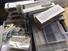
Elsewhere on WT, you may have noted I’ve been tracklaying on my test plank. The time had come to get serious about the boxes that had been slowly gathering dust on the top of my build queue shelf. At first blush, it was a daunting mass of all sorts. I spent a while sorting, unwrapping and generally trying to work out what I had taken on.
91B45DC6-C58C-4106-9B16-D8855C890BAC.jpeg

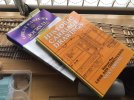
Knowing next to nothing about things Great Eastern Railway, the pile of reference material made a good read. With a slightly better understanding of what the coaches were and what they looked like, I began to sort stuff out.
86900FB3-1A95-44E4-9817-6859B06ADEBF.jpeg

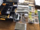
I have spent this morning going through lots of bags of castings. To try and be methodical about this multiple build - there will be 16 50ft coaches to start with - I separated castings into various tubs. Bogie details, underframe, body details, roof details. The original builder had done quite a good job on the sides, ends and underframes, so all I need to do is clean them and make and minor repairs as necessary. There are five builds to start, and I’m thinking I might kick off with one of them to familiarise myself with the way they are supposed to be assembled.

Discussion has been had about couplings, roofs and gangways. It is expected there will be two complete rakes of coaches, topped and tailed by brake thirds. The outer ends of the brakes will have good detailing, and Dingham couplers. The rest will be joined together with some form of semi-permanent coupling, and probably cardboard-style gangways. The kit roofs are vacuum formed styrene sheet, and although almost three decades old they are still in relatively good order. Nevertheless, the client wants to go for aluminium extruded section roofs, so we’ll have to order some from Wizard Models. I have plenty to occupy me before I get that far! Aside from the supplied interior partitions, it’s been agreed that no seating need be fitted.

In a future post, I shall give a bit more detail on what the various diagrams are, and how we hope things will end up. Let the adventure begin!
 

AJC

Western Thunderer
You’ll be fine - if Justin has has a hand in the design the bogies will all fit together and work properly. That said, you’re used to the big stuff, it will seem small!

Adam
 

Heather Kay

Western Thunderer
Is that an etch for a single bogie or a pair? It’s just one, isn’t it?

4mm?


oooo, ’ek!

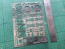
That’s one fret. It has a friend. There are alternate sides depending on how you want the footboards. The D&S kits have bogies in them, but don’t have any brake rigging. With 4mm I can get more on the bench at once, though, so there’s a bright side. ;)

You’ll be fine - if Justin has has a hand in the design the bogies will all fit together and work properly. That said, you’re used to the big stuff, it will seem small!

Cheers, Adam. They do look well thought out. Once the guitar string gets here, I can get on and put a pair together. The hardest bit will probably be grinding out the axlebox castings so the top hat bearings can slide up and down.
 

Daddyman

Western Thunderer
Heather: the benefit of some of my experiences with the bogies:

1. With the inner frame (the biggest part at top right of the etch in your photo), make sure that the right-angle joints between the sides, top and ends are very strong. This is because the forces involved in taking the wheels in and out are considerable, and can rip the corners apart. At the same time that you're making this joint as strong as possible, make sure you don't gum up the (very) nearby spring carrier holes with solder.
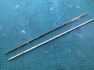
2. The advice I received from Dave Bradwell, no less, was to use two different strengths of guitar string - 9 (say) for the bolsters and 10 (say) for the axleboxes - without this, apparently, the coach won't know what to do in terms of roll. If you've only got one thickness of strings on order, Strings Direct are very fast - you tend to get things the next day.
3. Re the bearing carriers (the dumbbell-shaped things down the LHS of the etch), I can't see how Mark manages them the way he does in the instructions: these are supposed to be folded with the half etch between the two halves on the outside, the channel for the guitar spring on the inside, and with the half etched area for the top-hat bearing's rim on the inside and therefore not used. However, I found that even with slightly short axles (25.90 rather than 26.00), I needed that half-etched space for the bearing rim; otherwise, the axles were pushing the bearings out, and with them the sides of the bogies, taking them off vertical and threatening to split the aforementioned corners. With this in mind, I always flip the spring carriers - putting the central half etch on the inside of the fold.
4. The precision of Justin's etching is absolute - I sometimes feel a little bit too absolute (in the nicest possible sense), so that the spring carriers when folded down can push the bogie side frames off vertical. Perhaps take any cusp off them first? I've considered folding them down before folding the sides down, so as to be able to give them a slight rub with emery - that's another possibility.
5. Mark's step brackets are in the higher position - perfectly correct for many prototypes, but wrong for later North Eastern (and I think for Great Northern) bogies, which have them lower relative to the axleboxes. I'm not sure for the GER. If they are too high, this will play havoc with your central footboards between bogies (if your coach has them - they were removed in the late 1930s on ex-NER stock), which should be the same height - though having said that, the chances of the D&S etches for these latter lining up with the steps on the bogies is slim to nothing, whatever height the bogie steps are at. I make my own brackets for both bogie steps and (once the carriage weight, spring strength, and general sit is known, and the bogies are no longer jumping about) for the long footboards too, using 0.6 wire filed flat in each case. I can show this in a photo if it would help. It took me three months to work all the heights out, and the solution involves lots of careful jigging and even more (less careful) swearing. But if you have no central footboards, then you're laughing.

That's about all I think. If I remember anything else I'll let you know!

David.
 
Last edited:
Starting to build a coach

Heather Kay

Western Thunderer
David, thank you for your post. It got me thinking, which is usually a good thing.

I decided it would useful to try to find images of these coaches. Unfortunately, period images are hard to come by - and I spent a good while seeking them, believe me. The client's reference material has photos, but they tend to be of the coaches towards the end of their working lives in BR livery. By then, all the updates and modifications had been done. Perhaps I should set out the scope of this job before I get too much further.

The aim is to produce two full rakes of eight gangwayed coaches. I’m still very hazy about the make-up of each rake, because the number of coaches doesn’t add up. At the last assessment, the coaches are:

  • Diagram 227 1st/3rd Composite, 3 number
  • Diagram 419 3rd, 7 number
  • Diagram 541 3rd Brake, 6 number

If you recall, I am ignoring the Isinglass Quints at this stage. Now I’m questioning myself as to whether it’s two 8-coach rakes. I think I will need to hail Shropshire and settle the question.

Either way, I have 16 coaches to build. Twelve have already been started, with floor/underframe, body sides and ends mostly assembled. Four are new builds, plus all those bogies. The guitar string turned up yesterday, by the way.

While I was waiting for the string, and having thoroughly confused myself trying to work out combinations of braking, lighting and step boards, I decided I could do worse than actually get stuck into some construction. I chose a D.227 Composite, and aimed to put together the floor/underframe to see how long it would take.

0878DC06-3A20-4B49-89C7-F85517262573.jpeg

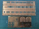
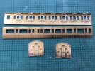
I forgot to take a photo of the floor fret. I’ll do it on another build, so make do with the body sides and ends. These D&S kits have a copyright year of 1984. That they’re still being produced, and still look this good, shows the care with which they were designed. The instructions, though, leave a lot to be desired. They’re not as bad as the classic ABS intensely-typewritten sheet with few diagrams, but not far off. It took a couple of reads to catch the way Mr Pinnock was thinking, but I got there.

E8B4843E-23E7-4743-BA7E-3D0E481151D8.jpeg

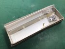
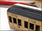
As well as the brass, in the box we find styrene in sheet and strip form, brass wire and a small bag of castings and fixings. There’s also the vacuum-formed roof. I know many pooh-pooh the supplied roof, and I understand why. I have been looking at alternatives, which chiefly come down to aluminium extrusions, and I will acquire an example to try for size. I am also quite willing to try the plastic out. The material is thick, the form quite rigid, and even the ancient stuff from the original kits still seems okay. Styrene has a habit of yellowing and becoming brittle over time, but there’s no sign of that on roof mouldings that must be at least 20 years old. I am formulating an idea or two to help keep the shape, but let’s just leave it that I am happy to try and use the plastic roof, and so is my client.

1D031679-F1B7-4C07-8525-B35EADA15315.jpeg

64C061BE-A9B1-486C-A63E-C78DE5288E15.jpeg

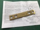
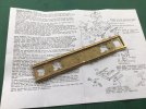
Posed on the instructions is a floor/underframe. Construction was fairly straightforward. Most of it fitted without problems. It took me, including fettling the parts, a lot less time than I thought. Still to be fitted are the queen posts and truss rods. I don’t need vacuum cylinders or battery boxes, but I will need to work out how the new bogies will fit. The kit bogies may have been more than adequate for the job, but you know clients! The bogie detail castings will be used, of course.

I can plough on with construction quite happily. The basic frames and bodies didn’t change an awful lot during these coaches' lives. The real things were built over about 15 years, in various lots, starting in the 1900s. They were intended for services from London to Norfolk, the so-called Norfolk Coast Express. Many survived into the 1950s, some ending their lives as departmental vans. As built, the majority of the coaches were lit by gas, steam heated and Westinghouse braked. Conversion to electric lighting and vacuum braking began in the 1930s, and was all done by the end of that decade. The question of longitudinal steps arises, aligned with steps on the bogies. All vehicles were built with these lower step boards, but it seems logical to me the boards may have been removed when the electrical fittings were installed. So, for the 1928 period, I shall fit the steps. I will confirm this with the client.

So, what I really need is a clear image or drawing that shows the arrangement of brake rods for the Westinghouse system, as well as confirmation of where gas cylinders were fitted. That should keep me busy for a bit.
 

Daddyman

Western Thunderer
Hi Heather. As an alternative for the roofs, you could try the system used by the chap in MRJ275, which consisted of profiled plasticard formers at a number of points along the length of the carriage, which were then covered with plasticard planks, filled and sanded to profile. I was worried that the planks would sag between the formers, so kept the planks, but made a continuous former shown below (what you see here was later covered in filler, the black plasticard and white filler combination allowing me to see that the shape was perfectly even; in all, about two hours' work, spread over two evenings):
roof former inset.jpg
You will need to be careful that the ends on D&S kits are the right profile to allow the roof (in whatever form) to sit correctly relative to the sides. I don't know for GER carriages, but for NER ones at least, the roof on the real thing is recessed slightly into the ends above the top of the sides, which means the actual roof material (exclusive of the gutter/cornice) sits flush with the carriage sides. On the D&S ends the recess is too small, pushing the roof out too far and resulting in a very brow-beaten look to the carriages if built up unmodified. However, a little more recess can easily be filed out of the ends.
Re gas and underframe fittings, check who Danny had advising him on the GER carriages (mentioned in the instructions?): did they have any interest (and expertise) in GER carriages in your period? This is not the case with the NER ones, and the info given in the instructions has led to many howlers on people's models. As I think I mentioned in our off-stage conversation, Danny (or his advisors) assume carriages went straight from gas lighting to electric lighting, ignoring the fact that most carriages (NER ones at least) for most of their lives had gas-mantle lighting. Because this system used about a quarter as much gas as plain gas lighting, carriages were converted tout de suite to mantle, as soon as the technology was available (1905-ish) and works capacity would allow (I have seen no NER carriage in LNER days with plain gas lighting; all have been converted to mantle). This has a big impact on roof and underframe fittings - including the number of gas tanks. To give an example, the Transport Library image LSDC1151 (better to search this on Google than on the TL internal search) shows an ex-NER D.18 on the GE Section with no lamp hoods on the roof, and only one gas tank, whereas the D&S instructions tell modellers to fit hoods and two tanks. How this relates to ex-GER stock, I don't know, but some of this may be helpful.
Your point about electric lighting being the reason for the footboards disappearing hadn't occurred to me, and may well be a good guess. I'd always assumed it was either because the footboards had become rotten, or because they interfered with gauging, preventing the carriages being used as "go-anywhere" vehicles, though admittedly hadn't found either explanation very convincing. Carriages used on secondary stock that worked in out-of-the-way places tended to get electric lighting first, to do away with all the rigmarole of stationing a gas-refilling wagon out in the middle of nowhere (Alston, for example). I don't model main-line trains so have no idea whether carriages for such services were built with electric lights as a priority.
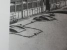
Re finding pictures of your period, I'm sure there are some. You'll turn them up in all sorts of places - any book that covers the 1920s or 1930s - the Ian Allan LNER Albums for a start. I've recently been looking for images of ex-NER horse boxes to see the lettering style in LNER days, and turned up a shot of one at Stirling in the early 1930s, peeping out from behind the subject of the photo, an ex-CR 439. You'll have to look in the backgrounds of photos and not for photos which take carriages as their subjects - there's little hope there. I'm sure you'll find loads of information once you shift focus in that way. You can then use a magnifying glass app on a smartphone (assuming you have one) to blow these up, digitise them and then blow up again on your computer screen to study them. I use one called "Magnifying Glass & Flashlight" (sic) by a company called EXA tools, available free in Google Stores. It's not as good as the one that came factory-fitted to my first Samsung phone, having annoying adverts, etc, but it's a start, and the quality is certainly good. Here's an example of the kind of thing I use it for (an image which incidentally gives the lie to D&S' claim that these elliptical-roofed carriages had twin rows of vents):
23-01-2022_14-41-21.jpg

Best,
David.
 

Heather Kay

Western Thunderer
Again, thanks David!

Rotten footboards is just as good an excuse as needing to access battery boxes easily. ;)

John Watling and Mike Brookes get namechecked in the instructions. The latter I know was a long-time GER Society member, and it's generally thought that the former knows everything there is to know about GER coaches.

I like the roof technique, but it’s not ideal for 16 models. :confused: I just checked an etched end with the plastic roof, and it’s not a million miles off, just needing a tiny adjustment with the file on the end radii.
CD451471-7F2C-4854-8F90-95A256EE0270.jpeg

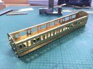
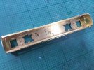
I think that’s fair progress. The ends have the hot soldering detail complete. I’m actually enjoying the tinyness of it. The kits are well thought through, particularly using the droplights to fix the upper and middle hinges in place, and provide some way to hold glazing. Whether I’m going to use it remains to be seen. One thing I’m puzzled about, and that is how to fix the body to the underframe. There doesn’t seem to be any place for slots or holes for bolts that I can see. I think I’ll have to assemble a body to see if I can figure it out.
 
And, lo! A body meets underframe

Heather Kay

Western Thunderer
37C47148-0218-451C-AEDB-59E5078112D0.jpeg

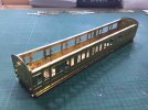
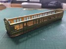
Hello, what have we here? Chuffed with that. I’ve tacked the body together so I could see how it worked with the underframe. I have some questions about that, but they don’t need airing here. It is probable, lacking any form of tab/slot mechanism or holes for a bolt to pass through (yes, I could drill some) the body will end up glued in place once it’s painted. I also still need to fit the bottom hinges, and do some fettling around the body.

Anyway, pleased with the progress. This exercise has given me a good idea how long a coach will take from scratch. I’ll carry on with underframe research, but I think a set of bogies should be next.
 

Daddyman

Western Thunderer
Looking good, Heather. If you notice, on your picture of the underframe, there are two holes either side of where the bogie pivot bolt would be - or the bogie centres if you prefer. The body-to-u/f fixing bolts go there. There should be some corresponding strips about 10mm wide that you need to solder across the body between the fold-over flanges at the bottom of each side - be careful because those strips are often the wrong length (both too long and too short depending on the kit). The problem with the set-up as originally designed is that the "boxes" that serve as an intermediate fixing point between bogie and u/f cover up the body-to-u/f bolts so that you have no access to them! This will not be a problem with the Miscellany bogies as you won't be using the "intermediate box".
David.
 

Mark Tatlow

Member
Hi Heather

Aghh, I recognise those - as you would imagine!!

I can't help you with how small they are; to me they seem fine and it is the 2mm guys are the ones that are nuts in my eyes!

I can offer some advice if you get stuck along the way, both with the bogies and 4mm coach building in general. I need to leave it to others about the prototype though, even if you are using my father's book!

Definitely do a pair of the bogies in the first instance as a road test as there is definitely a knack to them; repeat with a second set before going into batch production. My first pair took the better part of a weekend (a lot of which was grinding out really hard cast brass axleboxes); I can now do a pair in an evening (if perhaps not a short evening!) but I have built a good dozen.

David has given you some good steers, which I generally echo and would add to:
  1. Inner frame strength - I agree with David this is an area that needs good strength. I use a high melt solder as I find it is as hard as rock! In addition, please note that Fox bogies were pressed steel, so their edges including the corners are rounded. This simply could not be included in the etch process so you need to get your files out once the basic frame is built - the photos in the instructions show this
  2. Spring strength - I don't really have an opinion on this as I use 10 thou on both but I would agree that if you use a lighter gauge use it on the bolster not the axles
  3. Spring carriers - I am coming around to David's view in that the spring carriers are a bit tight. I deal with it the same way in filing out the half etch on one side so that the bearing sits deeper in the carrier. I also subsequently file a slight grove to the base of the carrier and base of the bearing so that it is easier to pop the axles in/out.
  4. Cusp dimensions - again I have not really encountered this but a quick waft with the file before bending would do not harm;
  5. Step brackets - a bit of an issue that there are multiple different prototype solutions. You will find that the inner frames do not have etch lines so as long as you are aware of the point, it is not too difficult to adjust the base design to achieve a different arrangement.
  6. Axlebox slots - unless your D&S castings are different to those that I am familiar with then the white metal is not that hard. I elongate the bearing hold provided by work with a scalpel - less than an hour for a pair of bogies.
  7. Wheels - partly because I am a slightly messy solderer (or fluxer if that is a thing!) I use a set of Branchlines wheels to build all etched kits now. These are nickel silver so don't rust and they are also nearly always very true. This is a clue that Gibson wheels are not always so it pays to check that they are on the axles square and to the correct back to back before final assembly.
  8. Roofs - a pet hate of mine is roofs that are not secure and look as if they have san-andreas faults between sides/ends and the roof. I thus create either tangs that come down from the roof to provide a point to bolt to by the floor or long bolts that run up in the coach body to achieve the same. A few photos of the former can be seen here Midland Six Wheeled Full Brakes
  9. Footboards - I had always thought (I think with justification) that the lower footboards slowly disappeared from the start of the grouping era was because by this time there were few stations with really low platforms, so the lower footboard was not required for general punters to get into the compartments and they were a maintenance issue due to rotting. The exception was for the guard to access the alarm gear which might be activated anywhere so the fella had to climb from the ballast. Thus, if you are modelling these in the grouping era, you are going to look into whether they still had full, part or not footboards. The etches do not have no foot boards built into the design, so you have to file one off from the single end option.
Hope this helps. I only drop into this forum from time to time, so if you do have questions send me an email as it will get a faster answer!
 

James Spooner

Western Thunderer
Hi Heather

i recognise those carriages, having made up a number of Dan’s GER carriage kits. Actually, only being an EM gauge modeller, rather than P4, I have always used his bogies. The first carriage I made used the compensation system offered in the kit, which works fine but does increase the rolling resistance somewhat. For succeeding carriages I just built the bogies with no compensation and, being EM, haven’t had any problems.

Roofs have been mentioned above. Again, I have always used the roofs supplied in the kit, but have added in a false ceiling from plasticard sheet, which sits on the folded over tabs at the top of the sides, with small tabs extending just beyond the ends. The moulded roof can be glued to this with solvent and that provides a sufficiently rigid roof structure.

To be honest, I just love those kits as Dan obviously put a lot of thought and care into their design and they go together much better than many more recent products for other manufacturers.

Nigel
 

Heather Kay

Western Thunderer
David, Mark and Nigel, thank you all for comments and input.

David, I think I’ve located the cross beams you refer to. Oddly, they don’t get mentioned - that I’ve noticed - in the instructions.

Mark, this is my first 4mm commission job, and it’s a bit of a culture shock! An enjoyable shock, but shock nonetheless. It’s just a case of recalibrating the eyeballs and realising some details that are considered essential at 7mm scale just aren’t all that important at this size!

Nigel, I’m not sure we needed to go to the relative complexity of the Romney bogies, but clients know what they want. Having grappled with a Kemilway 7mm kits of late, these kits look quite simple by comparison. As Mark says, consider the first pair as a technical run-through and dress rehearsal in the provinces before embarking on the full West End run.

Domestic duties this morning, so I probably won’t get back to the bench until this afternoon. The first job will be to make a small adjustment to the fit of one of the ends. The test fit yesterday showed the body shell to be a little long for the chassis, and I think I know where.
 

Heather Kay

Western Thunderer
After a slightly truncated session, this is where we are.

2500848C-3461-4718-AC78-7B51A0B53003.jpeg

I found some parts that were probably intended for the kit bogie setup, but which fitted across the body and aligned with the bolt holes in the floor. I will need a little packing under the centres, because the bolts pull it all down.

F9C3FABC-40D6-4672-94A3-E865290585DB.jpeg

7DEC4138-B7DE-46C9-8BC6-6F8423181EE5.jpeg

Fitting the bottom hinges proved I need larger recesses in the bottom L-plate to clear the holes: noted for the next one on the stocks. I’ve also had to drill through the commode handle holes so wire can be fitted later. One side had pre-etched holes, one didn’t. With the end fit adjusted inwards just a tiny bit, less than a millimetre all told, the body shell now sits between the headstock brackets as it should. With the body in place, I can see one corner still needs some adjustment, but all told it’s coming together well.

Bogies should be next, so mating them to the floor unit can be worked out. I will leave underfloor details and any interior work until I’m happy with the coach running. Perhaps I should work up the other three new builds to the same point. I think I should engineer a jig so sides and ends can be held in some kind of register while tacking things together.

Things still to acquire are gangways. It's funny how changing scale makes all my regular suppliers unusable. It’s taken me a while to acclimatise to checking out stocks at Wizard Models and Dart Castings!
 

James Spooner

Western Thunderer
Heather

On gangways, Dan did produce an etch for the ex GER coaches. I bought some more GER 50’ coaches quite recently from him and they included the gangway etches so a phone call to him might yield some results.

Nigel
 

Heather Kay

Western Thunderer
On gangways, Dan did produce an etch for the ex GER coaches.

It was intimated in the 1980s instructions such things were being designed, so I assumed they were available by now. The plan is to only use detailed gangways on the outer ends of a rake, with cardboard concertina style gangways in between.
 
Building an underframe

Heather Kay

Western Thunderer
As promised, here is a sequence to show how an underframe goes together.

0CC14349-C728-43B5-A751-1070E04CCD83.jpeg

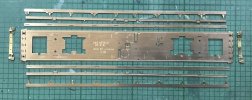
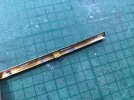
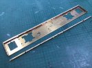
First, here are the parts laid out after having had etched cusps and tags cleaned up. The solebars are made of an upright, with the row of slots in it where the step boards fit, and the bottom flange.

9AEB349B-0949-41EF-997D-2001E73FA0BE.jpeg

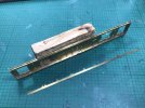
This time round, I folded the headstocks up before I started. There’s an overlay that goes on, seen in the first picture. I leave that until all the other bits are done.

6F2E248F-771F-41BB-A037-AFD0B2BAE253.jpeg

It is suggested the easiest way to make the solebars is to solder the bottom flange to the side first to make a T. Care must be taken to get the side part the right way up. The row of slots are not central on the side, and the part must be orientated so the slots are nearer the floor of the coach. The bottom flange also has various pegs, which go inside the frame.

96D58F83-AF9B-4EEE-8724-88D6B009501F.jpeg

I tack the flange to the side rather than attempt to run a bead. A bead not essential for a strong joint, and avoids heat stressing the parts. Enough tacks are used to hold things in place, as true as possible. This image also shows the side is longer than the flange, and you can just make out a slight recess at the end of the side. This slips under the headstock.

BFDFE690-7D99-4100-BCD3-2342F9EB9229.jpeg

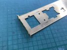
The solebar assemblies can now be tack-soldered to the floor. There is a half-etched slot for them to sit in.

98F4C15D-66CC-4D70-AFC0-D3394DF36F4C.jpeg

The footboards are next, and are probably the fiddliest part. You can see on the board in front, waiting to be fitted, a series of tangs. The centre tangs are half-etched and designed fold down and become brackets to hold the steam heating pipe (and vacuum pipe if fitted) as they run down the outside of the solebar under the footboards. The other tangs fit into the slots in the solebar. The fiddly part is trying to get solder in under the inner lip of the bottom flange. It’s a bit messy, but is possible, and the joins don’t need to be all that strong. I realised I only need one set of the pipe brackets, but I always forget which side the steam pipe runs. I’ll nip the incorrect ones off later, when I come to fit the pipework and other underframe details.

01959DBE-5D95-49B4-B5C4-1C125C2F7179.jpeg

The headstock overlays are sweated on the ends, and the steps folded down. I dab a bit of solder in to reinforce the fold, otherwise the steps are accidentally bent back and forth and eventually would snap off.

And that’s it. The fiddly details and mounting the bogies are all to come, but the next stage will be detailing up the sides and ends. I’ve decided to carry in and build up the carcasses for now, and probably clean up and assemble the original 12 part-assembled coaches so everything is at the same point.
 
Top