SimonD’s workbench

michael mott

Western Thunderer
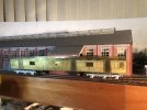
Great work on the offices general appearance Simon, I am thinking that it might need a little "weathering" it looks a bit like the showroom catalogues that depicts new homes. Perhaps a conservative amount of general clutter and of course workers.

Michael
 

simond

Western Thunderer
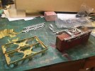
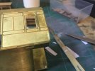
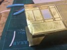
Time for some brass. I purchased a multi-hand Blacksmith kit of a diagram M14, 70’ newspaper van some weeks back. The couriers managed to damage the contents despite it being well packed, I suspect the dropped it on one end, from some height, which partially crumpled the ends of the etched body. Frustrating but not too difficult to sort out.
1646564510784.jpeg

1646564558983.jpeg

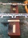
A few taps with a suitable bit of wood onto another bit of wood seems to have sorted it. Any further fettling will be carried out when I assemble. It’s more obvious on the inside than the outside, anyway!
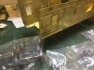
image.jpg

So, apart from the partially pre-formed body, whaddya get?
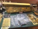
image.jpg

two bogie etches, cast w/m side frames, lots of w/m details for bogie & underframe, preformed roof , etches for ends, mid body formers, buffer beams solebars, steps, trusses, and corridor connectors. And a set of wheels included.

I purchased some milled brass angle at Kettering yesterday from which to make the gutters.

These were “concertina” vehicles in that the doors were flat, sliding inside the curve of the tumblehome. The kit allows for this by providing door reveals as part of the body etch, and separate door etches.
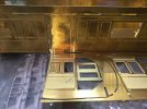
image.jpg

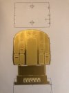
This somewhat arty shot shows both, and suggests that it won’t really work as etched. The doors are consistently 20.2mm wide and the spaces are 21.8. Folding the reveals back will not look great, and there will be a gap to fill where the tumblehome tries to meet the reveals. Compromise time. I guess the doorways are a full 3’ wide, so the doors are marginally too narrow, and the holes are rather too wide. I’m going to make 8 bulkheads from 0.8mm material, to form the reveals, and solder them to the body so the edges show. that will close the gap to a size that the door etches will fill.

Rather than laboriously fretsaw and file to a line, I’ll draw them on CAD, and then CNC mill them when I’ve got time at work. I’ll also make a wooden form on which to panel-beat the tumblehome.

Drawing & photo references, Harris & Russell as usual:
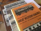
image.jpg
 
Last edited:

Dog Star

Western Thunderer
I have a recollection that (the late) Raymond Walley built this kit... as he also built a Dreadnought so both of his write-ups ought to be of interest to you.

regards, Graham
 

simond

Western Thunderer
I have a recollection that (the late) Raymond Walley built this kit... as he also built a Dreadnought so both of his write-ups ought to be of interest to you.

regards, Graham
Thanks Graham, Daifly also mentioned this. I shall go looking.

currently checking numbers.

the Kit says diagram M14 & has four sliding doors, three large and one small window per side, looks like a brake cabin at one end. there were no instructions or prototype notes.

Russell says M14, lot 1062, three sliding doors, four windows, and M14 lot 1178, four sliding doors, three large windows, Guard’s door both sides, one end. Figs 100 & 102. These look like the body of the kit. Numbers 876 & 877.
(Diag M15 was 3-door and built between the two M14 lots, presumably just to confuse me)

Harris says lot 1178, built 29/10/1910, numbers 876 & 877 for Fishguard boat stock.

ok, we have numbers, diagram, build date and a couple of photos, and Raymond’s build notes. He had some issues with this kit too, and identified the door problem I mentioned above - he observes that the kit had probably been “blown up” from a 4mm design, and I’d concur. He also mentions the rather daft arrangement of bogie pivot and centre axle coinciding. An offset pivot point for the bogie beckons. I think I’ll start there.

more soon
Simon
 
Last edited:

simond

Western Thunderer
Decisions, decisions…

image.jpg

the box contains the etch brass fold-up bogies along with springs & axleboxes to make up per the Raymond Walley article, and a pair of Cavalier cast w/m bogies of the same pattern. As Raymond had said, the holes in the etch are huge compared to the bearings.

Both options have the bogie pivot bolt coincident with the middle axle. Would it have been so challenging to move it off centre by 5mm or so? It really doesn’t need to be in the middle of the bogie!

looks like the options are
build Cavalier bogies as designed (with offset pivot) - they are nicely detailed, but still need steps adding.
build etched bogies per Raymond (with offset pivot) - stronger than w/m but need steps adding - perhaps easier, and needs bearings supporting in the huge holes. Might offer opportunity to provide springing a/o compensation.
attempt to include some springing or equalisation in either
attempt to allow axles to be dropped out and fitted after paint.

Replacement of the nice cast frame on top of the Cavalier bogies with a piece of brass of suitable thickness (2.1mm) would kill several birds with a common stone, in that said piece of brass can be drilled & tapped to attach the bolsters, which can be soldered to the frames, and then be cut in half, allowing the bogie to be dismantled. It can also provide the offset pivot, but would not help with equalisation. It would be stronger than the w/m frame, but bogie dismantling would not stretch to the end transoms and brake gear.

I shall ponder a bit, but I think Cavalier bogies build non-compensated and non-dismantle-able will be the easiest route forwards, and adequate if I make sure the middle axle is 20 thou high so it can’t see-saw.
 
Last edited:

Phil O

Western Thunderer
I have just googled Raymond Walley and I see that I would need to be an 0 gauge guild member to access the content, which is a pity, as I have a couple to build in 4mm and any assistance would have been helpful.

I look forward to seeing your progress Simon.
 

Tim Watson

Western Thunderer
I have the Ersa I Con-I which goes well, but I have just ordered some new bits. They don’t seem to last that long, but I am always a bit generous with the phosphoric acid flux.

My other big old irons haven’t been used in anger for ages, but I do quite often use a little gas flame when needed for really big stuff (3.5” gauge).

Tim
 

simond

Western Thunderer
Bogies!

I decided to use the Cavalier w/m ones as they are nicely detailed, suitably heavy and look like less work than the brass ones for a similar result

First thing, inevitably the holes for the bearings are too shallow so they needed drilling out - cue space-age bit of wood with bits of stirrers glued to it - the axle box fits in the hole, the spring sits against the guide and the double thickness supports the lower edge. Set drill depth, drill 8 holes.

Then I need to ensure the middle axles are not going to act as see-saw pivots, so drill 4 more holes a bit larger, and solder some slotted guides over them - the wheels can then come along for the ride, stay parallel but carry no load. Easier than compensation.

image.jpg

I shall now solder the guides to the inside of the bogie frames and see if it all goes together ok.

Then I’ll make new bogie top plates with an offset pivot - probably nearer the ends of the coach to marginally reduce buffer throw.
 

Peter Cross

Western Thunderer
We’ll overlook the wheelbase being 86mm, when 84 would somehow be expected…
My K3, the cast bogies are 8' 3" not 8' 6". I'm sure it can't be noticed even when next to correct length bogies. Just need to make sure it neither leaves a gap, or hits what it's not supposed to.
 

simond

Western Thunderer
It’s a big old beast…image.jpg

And my efforts to generate a profile to make the bulkheads seem to have paid off - I need 8 of them so I’ll do them on the CNC mill at work

image.jpg

I’m pretty pleased with that - it appears to be a pretty consistent 0.5mm either side
 

simond

Western Thunderer
Ok, guys, this one has me puzzled. There are no instructions (apart from the gangways, bizarrely) so I’m flying blind.

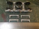
Underside of the bogie, and the transoms with attached brake shoes.

image.jpg

The lower pair, nearer the rule fit against the crossbeam, and the shoes sit nicely relative to the wheels, though there is probably enough room for S7 wheelsets between the shoes.

The other pair appear to be intended to fit at the ends of the bogies, but don’t. The shoes are 35mm between the shoes, which would almost do Irish gauge, and the curious lumps on which the shoes & hangers are mounted interfere with the cast lugs against which it appears the transoms should be soldered.

image.jpg

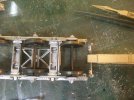
The inboard ones are ok, but the outboard ones won’t fit. I could cut the lugs back, but the shoes are way outboard of the wheels, or I could cut the shoes off the transom, but the whitemetal is rather soft and I doubt they’d survive in useable condition, so I think I’ll make new transoms from brass angle, and then see about making a representation of the brakes from resin, which will avoid any shorts.

Other suggestions most welcome!
 

Yorkshire Dave

Western Thunderer
I think I’ll make new transoms from brass angle, and then see about making a representation of the brakes from resin, which will avoid any shorts.

It may be the wise solution given how tight it looks in there. And you really wouldn't want intermittent shorts caused by this vehicle (or any other for that matter) - especially as you operate DCC.

We’ll overlook the wheelbase being 86mm, when 84 would somehow be expected…

It's amazing how some kit manufacturers get things fundemantally wrong - albeit 2mm.
 

simond

Western Thunderer
Thanks Dave

it‘s getting on a bit, definitely pre-DCC, and pre CAD too….

but, the bogies look nice, and the etches are clean and well etched, so, it’ll be a good layout vehicle, and my third 70 footer.
 

mickoo

Western Thunderer
Drawing & photo references, Harris & Russell as usual:

View attachment 157852
Simon,

Long shot, do any of these books contain drawings for H13 Dining cars, preferably with the 6 wheel bogies?

It's for an up coming project and I already know they were updated so need to research them in the 50-60's guise, however the base (as built) drawings will be of use.

Nice repair on the dropped end :thumbs:
 

simond

Western Thunderer
Mick,

not much I’m afraid.

two photos in Russell, pg 37, one with 6W bogies, one with plate frame 4W. Three lots of Second class diners built under lots 1114, 5 & 8 in 1906. They were later downgraded to third class.

He refers to an interior shot in part 1 pg 223, which together with the first class diner on the facing page, demonstrates the level of luxury railways ought to provide!

Harris states that lot 1114 were the H13 and that these were First class diners. Numbers (8)401-4 July 1906, and 1115 were likewise but to dia H14 and completed in June of that year numbers (8)405 & 6

Lot 1118 were H13 again, First class p, numbers (8)407-412 completed September 06.

No specific drawings in Harris either, nor in Wild Swan “Official drawings No3 GW Coaches” but there are several supporting “typical” sections, views etc.

atb
Simon
 

mickoo

Western Thunderer
Simon,

Appreciated, my problem is that the client requires a late service model, late 50's I think and by that time they had gone through several upgrades and rebuilds, internally and externally.

The last rebuild had steel skins overlaid on the exteriors but some paneling appears to remain and that's the problem, the photos I have are quite poor photo copies so it's hard to determine how much paneling was covered and how much remained, it also looks like the end wall tumblehome was made flush in later lives. Some appear to have smooth lower sides but others still retain a hint of small panels with vertical joints below the waist line beading that appears to be retained through out their lives.

The coach in question is W9529W and all I really need right now are good quality views of each side and I've no issue having to buy them if needed, I'm sure there will be works photos after the rebuilds or in service somewhere, but where I've as yet to find.

I have the Official drawings #3 booklet and can get a decent frame up from that and basic shell, its the later years external appearance that's a stumbling block right now.

Two of the photcopies must come from one of those three books you have but there's no indication which book.

Lots, 1114, 1115, 1118 page 37, Fig 46 & 47 (9526 in fig 47 in BR maroon is of particular interest)

Diagram H11, H12, H13, no page but Figs, 150, 151, 152 (9527 in fig 152 with steel paneling is of particular interest all be it in GWR colours)

I'd happily buy the books, if I knew which ones to get :cool:
 

simond

Western Thunderer
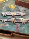
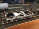
Bogie progress. I now have two like this. Runs sweetly, centre axle has loads of vertical play, some side play, and isn’t complete b to get on the track.

image.jpg

needs bolsters & steps adding, and a coat of rattle can black. I’ll add brakes at some point in the future. They’ve been added to the “Ill print these if and when I buy a resin printer” list.

S
 
Top