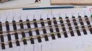
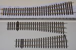
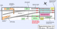
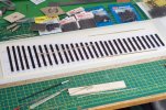
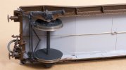
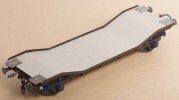
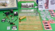
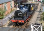
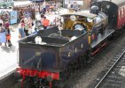
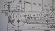
I have completed my A-6 as far as I can take it before installation onto a layout and wiring it up. I have realised, all the plain track is going to have to be hand-made (so I can have pre-grouping sleepers) so this one is 31.5 mm gauge throughout. Here are some photos with notes to record my thoughts along the way.
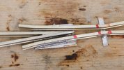
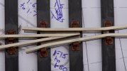
I think this is how a vee should be built. The rails were shaped and soldered together by Waverley Models. I have given their vee a blunt nose and a little curvature on the top. Looking at the wing rails, I can do neater soldering than this but speed was important to make sure the vee stayed intact.
I am happy with broad alignment marks from the red Sharpie. I know whether I am aiming for the middle or one end of a mark. This crossing is a bit tighter than my last attempt in that the feeler gauges are a light interference fit not a clearance fit in the flangeways.
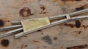
The brass plate gives a reasonably large surface area to glue the crossing down onto the timbers.
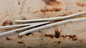
This is the crossing after scrubbing with Cif stainless steel cleaner but before final cleaning up.
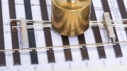
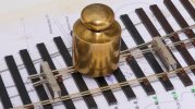
There is a 0.5 mm styrene shim between the timbers and the crossing. The shim has cyano on its top surface and Butanone on its underneath. 500 grams left here for an hour while I had breakfast.
I have missed out some chairs on the stock rail here to make room for full chairs to hold the check rail. The Peco timbers are hollow underneath but their inverted U section will be hidden by ballast.
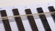
This is Peco BH style rail, I have filed away the foot of the rail to help the blade to sit flush. The slide chairs are Kalgarin/Permaway. Peco make these as well but they seem too long to me.
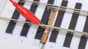
Most of the battle with awkward soldering is making a temporary fixture to hold everything in place. Offcut of rail bent into a shallow elbow and jammed under a spare copperclad sleeper. Croc clip is gentle but enough.
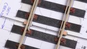
This time I am trying 0.4 mm piano wire for the tiebar. It doesn’t seem very strong but it is stronger than the solder joints at each end. The scraps of copperclad at each end are from an idea by Jim Snowdon published in the GOG Gazette, they keep the tops of the blades in line with the tops of the stock rails.
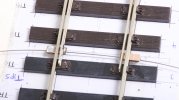
I have read somewhere, the blades should settle to a neutral position mid-way. I don’t know why this is needed but I seem to have achieved it here.
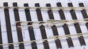
These chairs are a mix of C&L (light brown), Peco (foreground) and Permaway (middle and top).
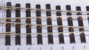
The kit provided long wing rails and short point blades. This was going to put the insulated gaps in an unconventional location. I decided to cut new gaps in the usual place and solder the blades end onto the wing rails. I am hoping this "workmanship" will disappear with some Araldite in the gaps and a few coats of paint especially over the solder. There is something scary about soldering so close to ABS.
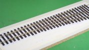
If 0 gauge is 32 mm gauge and 0-SF is 31 mm gauge, the 0-MF as I have aimed for here is probably a safe bet for me because small errors either side of the nominal 31.5 mm should leave the gauge within the extremes of what I consider to be the sloppiest and tightest standards and all of my stock will run. The flangeway gaps are much the same as those on a Peco Setrack point for H0, half the linear scale, which might be food for thought.
I can feel a tiny wheel drop with Slater’s wagon wheels but I cannot see it. If the crossing was 1:5 instead of 1:6 there wouldn’t be any wheel drop at all.
I can put this all away now, knowing the points are ready when I come to build a layout.

