The Heybridge Railway, 1889 to 1913

Richard Gawler

Western Thunderer
I am using a micro flame torch instead of the iron wherever I can, and I am using far less solder and needing far less cleaning up afterwards. The torch was a good buy. I put the solder on the inside of the joint and apply the heat on the outside, and the flux does the rest of the work.

The 100 degree solder is intriguing. Apparently, when this forms an alloy with white metal the result has a higher melting point than either the solder or the white metal. There are places on my coping where the solder joint is well over 0.5 mm thick but I cannot see where the solder meets the coping. I never got the hang of chemistry, but the solder (Carr's) is 25% tin / 25% lead / 50% bismuth. I don't have a spec for the whitemetal.

At the moment, I am more interesting in trying to achieve a reasonable standard of construction than aiming for scale accuracy or correctness to prototype. So the copings are going to look overscale in thickness but I will be happy as long as they look neat and tidy.

DSC_0919.jpg
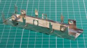
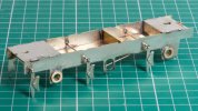
I have got the footplate assembly underway and this looks as though it will sit flat under the body without tell-tale gaps. However I am going to have to move the guard irons inwards, otherwise they will foul the buffers (Markits).

The side frames are from the Alan Gibson kit for a Holden E4. These needed a lot of fettling, the oval cut outs looked as though the artwork had been hand-drawn, but I am happy with them now. I want to build the chassis and install the wheels before I add the castings for the axle boxes, to make sure the castings line up with the axles.
 

Chas Levin

Western Thunderer
Nice work Richard.

Interesting note on the 100 degree solder and WM combo's resultant melting point. I believe that make's it the opposite of a eutectic alloy (such as 70 degree solder) where the alloy metls at a lower temperature than the melting point of any sinlge constituent.

There's clearly some significant differences between the 100 and the more common 70 and 145, as the 100 bonds to a wider variety of metals, doesn't it?
 

Richard Gawler

Western Thunderer
Looking at the constituents of soft solder, the 188, 145 and 70 degree ones I have are alloys of tin and lead. Lacking detailed specifications I guess the differences between them are the proportions of these two metals. The 100 degree solder is different in that it contains bismuth.

I wrote down a list of the metals I want to use for model making:
  • Brass - copper and zinc
  • Nickel silver - copper, zinc and nickel
  • Machinable brass - copper, zinc and lead (I imagine this is used for lathe-turned detailing parts)
  • Phosphor bronze - copper and tin (and a trace of phosphorous)
  • White metal (I think this is usually a tin-copper alloy but I'm not sure)
  • Copper
  • Lead
  • Steel (buffer heads, axles and wheel tyres)
When I got to the end I realised everything I can solder using soft soldering techniques is copper or an alloy of copper.

I found out about 100 degree solder in a chance discussion at the club. I didn't know it existed. I haven't used 70 degree solder for anything except practice pieces and at the moment I can imagine selling it on or giving it away. I cannot think of a preferred use for 70 degree solder when the 100 degree product can be had.
 

Richard Gawler

Western Thunderer
Simon you are perfectly correct, and I should keep my 70 degree solder and have a fresh go with it one day.

The funny thing is, right now I am trying to work out how to install some Markits sprung buffers onto the tender buffer beam. I think I can find room for the steel shanks inside the outer frames (just), this is with the buffers at 39 mm centres. But there is no room for the nuts to thread onto the shanks. Perhaps a bit of wire soldered onto the shanks in lieu of the nuts would do the trick.
 

simond

Western Thunderer
It's a well known problem because we don't (typically) use self-contained buffers and the real thing doesn't have a 3" thick threaded shaft with a foot AF brass nut poking 18" out the back. And of course the prototype frames were more-or-less directly behind the buffers to provide the strength and stiffness just where required. Not daft, those old engineers...

solutions;
Make S/C buffers. Doable but tricky particularly on older stock with spindly buffer stocks, various methods have been proposed online and in books
Slot or otherwise cut away frames. Easy, and dependent on prototype, can be easily hidden by the steps, etc.
Rigid buffers. Anaethema!!!! perfectly reasonable solution, but might make coupling up challenging, depends on springs on couplings
 

Ian@StEnochs

Western Thunderer
Another solution to the tender buffer problem. Position the buffer at scale distance and reduce the thickness of the frame in way of the buffer shank. File, grinding disc, dentists burr or milling machine, depending on what tools you have.
File the tail of the buffer shank down to 1/2 it’s thickness and retain in the body by making a little bend, needless to say the flat runs against the frame and the bend only needs to be sufficient to keep the head in place.
There is also the bonus of two unused nuts to add to your spares box!
Ian.
 

Richard Gawler

Western Thunderer
DSC_0938.jpg
This is what I have done, after the first go at cleaning up. It is amazing how many pretty colours I can make by heating copper alloys too hot for too long.

The ring of solder on the buffer shank on the left is interesting. I imagined these buffers were turned from solid, but it seems they are in fact facbricated.

The frames are only 0.5 mm thick and already half-etched for the steps but I will remember the idea of thinning down the frames for future models.

DSC_0935.jpg

Keeping the 39 mm between buffer centres (1 mm underscale but so is the track!) and leaving the outer frames untouched (because I am so pleased with my soldering on these), I found just enough space to file a flat on each of the bosses at the back of the buffer shanks.

I expect there is more solder here than I really need but the buffer beam does take the brunt of the train during operations. Well that's my excuse anyway.

DSC_0936 (1).jpg
Having done this, the threaded spigot will pass through without filing it down but without space for a nut. I think putting a little bend on the spigot is my best bet for this model, and I can do this after the model is painted. The buffer heads are circular so cannot end up crooked.

I think buffer springing is important to try for. The springs won't operate often on my layout because the trains will be short, the wheels are free-running, and shunting will probably push the stock away. But the springing action will be noticeable on friend's layouts and at the club.

And so (!) . . . if there is anyone reading this who decided to make their 7mm Markits buffers solid and kept the springs for a rainy day, I would find one extra spring ever so helpful to replace the one now on my carpet :oops:
 

Paul Tomlinson

Western Thunderer
"I think putting a little bend on the spigot is my best bet"

You may have space to glue a short piece of brass tube over the threaded shank, failing that a length of heat-shrink tube, or drill a hole at right-angles through the buffer shank and insert a taper pin. Good luck with whatever method you choose.
 

Chas Levin

Western Thunderer
As Paul above, I was going to suggest glueing something. What would concern me in trying to bend the end spigot is that it looks fairly thick and strong and not very far in distance from the visible front end of the buffers, so I would worry that you might distort the buffer, or the housing, or tear something loose, in using sufficient force to achieve the bend.
 

Richard Gawler

Western Thunderer
I have had a go at filing down a nut but I don’t have the dexterity in my fingers to thread the result onto the buffer shank in the space available. And I have lost a second spring in the process of trying.

The threads on the spigots are almost touching the insides of the frames so heatshrink is going to lock things solid, which is a shame because this would be good to try.

I think the best approach for me will be to cut a small notch into the shanks and bend them across. I know I can do this and it will work, but it has to happen at the end of the build, after painting. The spigots are 10 BA, making a tiny cut into the spigot should weaken it enough to force the bend where I want it.
 
Last edited:

Ian@StEnochs

Western Thunderer
I have had a go at filing down a nut but I don’t have the dexterity in my fingers to thread the result onto the buffer shank in the space available. And I have lost a second spring in the process of trying.

The threads on the spigots are almost touching the insides of the frames so heatshrink is going to lock things solid, which is a shame because this would be good to try.

I think the best approach for me will be to cut a small notch into the shanks and bend them across. I know I can do this and it will work, but it has to happen at the end of the build, after painting. The spigots are 10 BA, making a tiny cut into the spigot should weaken it enough to force the bend where I want it.

Richard,

You don't need much of a bend on the shank to retain the head. I have done it often and my only tool is pair of fine flat pliers. Just make sure you mark both shanks and put the bend at the same place so that both heads protrude by the same amount. As you say done on final assembly after painting and perhaps chemically blacking the heads!

Ian.
 

michael080

Western Thunderer
Pauls proposal above with a taper pin might be less risky and it might be easier to get the same result on both buffers.

Michael
 

Richard Gawler

Western Thunderer
I don't want to dismiss the taper pin idea out of hand, but I imagine I will be needing a pillar drill with a vice (or a lathe with a vice on the cross slide) to attempt the drilling?

The diameter at the root of the thread is around 0.05 inches / 1.3 mm so there won't be much metal either side of the hole for the pin.
 

Mike W

Western Thunderer
If you have no success finding a replacement spring, and if the manufacturers can't help either (or another manufacturer of buffers?), then I am sure the correct one will be here:
They will sell one offs, they just cost more money.
Mike
 

Richard Gawler

Western Thunderer
Mind boggling!

I have found a compression spring originally intended for a 3-link coupling but small enough to go inside the Markits buffer shank. I can give this a try.

After building a couple of wagons with dumb buffers and another with rigid buffers and keeping the various unusued parts, it's a pity the wagon buffers are 12BA while the loco buffers are 10BA.
 

Richard Gawler

Western Thunderer
DSC_0945.jpg
There are two strips of brass which make up an external flange at the back of the tender. I had a bit of a think about these and decided the best approach was to fix the horizontal strip to the footplate and the vertical strip to the body.

DSC_0943.jpg
So the join is difficult to see when assembled and the body still lifts off to get at the r/c parts.

I wonder if I should have left some more room for the paint, I'm not sure. I can imagine painting this assembled and separating the parts after the paint is touch dry but before it fully hardens.

Edit: or simply elongate the two fixing holes in the footplate and slide the body a bit forwards.
 
Last edited:
Top