The Heybridge Railway, 1889 to 1913

. . major sub-assemblies of the completed model

Richard Gawler

Western Thunderer
DSC_0068.jpg

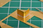
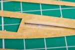
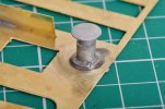
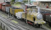
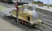
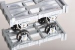
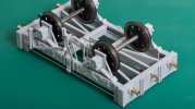
One final photo of Nellie to show the subassemblies I mentioned in post 235.

The pivot pin ended up being soldered solid onto the base for the crane, apart from this little changed from how I saw things then. This is as far as the model can be dismantled, apart from changing the wheels or motor or similar.

I have used BA screws to attach the chassis to the body and a metric screw for the trailing axle. They look quite similar at a glance. I would rather not do this again, I need to buy a few BA taps.

I have soldered the two rear sand pipes onto the body. I won't do this again either, they leave the body needing blocks of wood or similar to stand it on the workbench. Some brackets on the chassis would be better.
 

Richard Gawler

Western Thunderer
I have used BA screws to attach the chassis to the body and a metric screw for the trailing axle. They look quite similar at a glance. I would rather not do this again, I need to buy a few BA taps.
Nearly had a heart attack at the cost of full-price BA taps :eek:

I have ordered some 10 BA, British-made but entry level.
 

Rob Pulham

Western Thunderer
Nearly had a heart attack at the cost of full-price BA taps :eek:

I have ordered some 10 BA, British-made but entry level.
The set that I bought for £30 10/12 years ago is now Just over £50 - But it has 0-10ba taps and dies
BA Tap and Dies Set which reminds me, I broke and 8BA tap recently so I will need to replace it. Only the second tap that I have ever broken so I am not complaining.
 
Station platform shelter (assumed new in 1889)

Richard Gawler

Western Thunderer
The (fictional) Heybridge Railway had some kind of a passenger service, and for a while this was a public service. This was a pretty minimal provision - probably one brake third vehicle on a four-wheeled underframe. The service began at or soon after the inception of the line and the station was named 'Heybridge'. By 1907, most users had given up because it was easier to take the Witham train to Maldon East and walk the mile to Heybridge instead of walking from Langford (GER) to Langford Junction (HLLR). The GER breathed a sigh of relief and renamed Maldon East as 'Maldon and Heybridge’. The HLLR continued to provide an internal passenger service on a 'runs when required' basis; this was found useful for barge operators and employees of the canal company.

DSCF2706.jpg
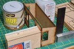
This is the kit for an 0 Gauge Station Shelter by Laser Cut Model Railways. I built this earlier this year, before I did my first metal wagon kit. The building went together really easily. It is a mixture of 2 mm MDF and 1 mm card.

2022-01-15 15.30.24.jpg
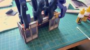
I added a strip of obechi across the front to hold it straight and make sure I don't push my thumb through the front of the model.

DSC_0108.jpg
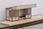
I get better colour with my new camera. I brush painted the model with Tamiya acrylics (not the Vallejo in the second photo). I tried to give it a fairly dowdy look.

DSC_0116.jpg
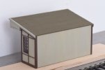
The primer was Rustins MDF Sealer followed by Halfords grey primer. I stopped painting the top coats on the rear wall before I got complete coverage to try to help the weatheirng when I come to it. The roof is sandpaper with pencil lines to represent the joins. I tried adding separate strips of sandpaper but they looked like a school project.

This was a particularly pleasant kit to build. I think it would work well in many settings, just change the colour palette to suit. I will add guttering and a down pipe if they are going to be visible on the layout, I can be quite lazy with this sort of thing.
 
Last edited:

Richard Gawler

Western Thunderer

This is my fifth video of Nellie. The loco never stalled during the filming (most of twenty minutes with re-takes) and I think this shows off the slow-speed performance pretty well. The controller is a hand-held feedback design purchased from All Components, this is similar to the one from the former Kent Panel Controls. The gearbox is a single-stage 40:1 worm/worm gear supplied by Jim Mcgeown.

It's fun making videos - the train barely moved twice its own length but the editing makes it look more. However, anything more sophisticated like tracking a moving train is going to need a second operator or some lumps of foam dropped at the ends of the tracks or indeed both. Some more lighting would be good too.
 
Last edited:
Rework of 'Nellie' : upgraded buffers

Richard Gawler

Western Thunderer
A friend suggested Nellie would benefit from some better buffers, and then a member of WT wrote to me with the same idea. We all seem to feel, the cast ones provided in the kit are perfectly adequate and keep the kit affordable, but better ones can be had. I have therefore indulged myself in some sprung GER style buffers from Walsall Model Engineering, and fitted these to the loco.
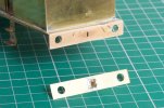
DSC_0139.jpg
Taking the cast buffers off was almost too easy. Opening up the holes for the new buffers was harder and I ended up with the rear buffer beam delaminating itself. Still it was good to be able to clean it up.
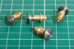
DSC_0135.jpg
The new buffers arrived with a somewhat conical shape. I understand, this is because a rounded-off convex buffer shape is difficult to make if you don't have a suitable CNC machine. So I removed the heads, covered them in black ink as a witness mark (Sharpie pen) and worked a small flat file over them.
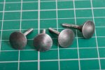
DSC_0138.jpg
Health and Safety people should now look DOWN to the next photo below. I put each head in the mini drill (20,000 rpm), ran the buffing wheel at half speed (5,000 rpm) and dressed the heads of the buffers. Then I treated them with Perma Blue.
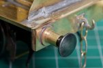
DSC_0142.jpg
I have also treated myself to a micro flame torch. I tinned the backs of the buffer stems bases using the iron I used for the rest of the build, and then sweated them into place with the torch. This photo rather shows how my soldering has changed since I started . . .
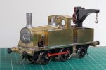
DSC_0144.jpg
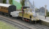
This is the result. Nellie is a freelance model but somehow she now has a bit of a "scale" aura about her.

I am hoping to take her to the West Essex club at Chadwell Heath tomorrow:drool:
 
Last edited:

allegheny1600

Western Thunderer
Hi Richard,
Nellie looks excellent, well done. May I suggest some thicker oil on/in the gears? I feel that I can hear the gears on your video and I wonder if that might cure it.
All I know is that it’s a trick I picked up during my 0 scale period.
Cheers,
John
 

Richard Gawler

Western Thunderer
Hi John!

Good point. In comparison, 'Blackwater' is pretty much silent.

I have dug out my sound pressure level meter. This is uncalibrated but does give an idea of what it happening. I held the meter one metre away from both locos. The meter records around 47 to 50 dBA (at one metre) from Nellie - a little quieter than a light tickly cough. The meter records nothing at all from Blackwater because the sound pressure level is below 40 dBA which is the lower threshold of the meter.

I think, the automatic gain control of the camcorder is making the most of the transmission noise from Nellie; but there is definitely room for improvement. I am thinking of trying some felt tucked up inside the boiler, some molybdenum grease on the gears, or re-meshing the gears. I am pretty happy with the meshing - I did this with the body removed of course - and I thought at the time the mechanism was rather sweet. I fancy trying the felt first.
 

Osgood

Western Thunderer
....
I have also treated myself to a micro flame torch. I tinned the backs of the buffer stems bases using the iron I used for the rest of the build, and then sweated them into place with the torch. This photo rather shows how my soldering has changed since I started . . .
.....
stems bases stocks :D

I hope to be not too far behind you in the soldering learning programme but from your progress it already looks like I'll be near the back of the class. :thumbs:
 
Trying out my new micro flame torch

Richard Gawler

Western Thunderer
stems bases stocks :D

I hope to be not too far behind you in the soldering learning programme but from your progress it already looks like I'll be near the back of the class. :thumbs:
The best tip I was given from a club member (as opposed to reading on a forum) is to cut the solder wire into little pieces e.g. Stanley kinfe. Then you always pick up a measured quantity on the bit. I worked out quite soon how far solder will go and I cut bits 1, 2 and 3 mm long to pick these up with the iron.

Solder goes a lot further using the micro torch because you don't end up wiping the bit along the margins of the joint and tinning them unecessarily as you go along. I did some test pieces after the buffers.

DSC_0152.jpg
About 2 mm of solder wire placed on the other side. Flame on the other side and solder pulled into the joint by the flux. The grid squares are 10 mm.

DSC_0153.jpg
Nickel silver wire on brass. About 1 mm of solder wire here, again it is flashing across and taken on its way by the flux.

DSC_0154.jpg
This is probably showing off but I nearly got away with it. I tinned the brass using the iron with the same 145 solder, then brought the flame in gently and slowly, heating the brass before placing the casting. Minor damage to the casting in the foreground. I think more practice would make this doable.
 

simond

Western Thunderer
I use my RSU on occasions, to solder w/m to brass, but the technique could be used with an iron or a flame.

Tin brass with conventional solder, tin w/m with low melt, apply flux, place casting and hold in place, apply tip to the other side of the brass and on-off in very short bursts til the low-melt melts. You can usually hold it with a finger.

if you tin the brass with ordinary solder, and then tin that with lowmelt (both as near one atom/molecule thick as you can) then applying a suitable iron to the underside of the brass creates a circle of melted low-melt which follows the tip of the iron as you move it around, thus very small w/m castings can be secured with very little risk.
 

Jordan

Mid-Western Thunderer
stems bases stocks :D

I hope to be not too far behind you in the soldering learning programme but from your progress it already looks like I'll be near the back of the class. :thumbs:
Welcome, welcome. Hard wooden stool, or comfy armchair? :)
 
Nellie's second outing (to the Ilford and West Essex club)

Richard Gawler

Western Thunderer
I took Nellie along to the open day at the Ilford and West Essex club earlier today.

The received opinion was, the motor starts particularly easily, and the model is quiet. I pointed out that another loco on the layout was pretty well silent in operation, and it was explained that it had a £120 motor/gearbox. While Nellie has a nicely-machined if simple worm/worm gear and a Chinese 1833 lookalike. I couldn't really hear Nellie in the club room with its background chatter.

I have now put some soft wadding over her motor and some molybdenum grease on her gears, but even if I think she is slightly quieter the sound level meter is reading about the same. I think, she is audibly "ok" to me.

This layout is 'Taw Magna' which is about 24 x 3 feet plus a 10 foot fiddle yard and it has some delightful pointwork. Nellie simply worked, no derailments and no stalls.

P1040286.jpg
I have a feeling she never ran through the loading gauge but I think she would have fitted.

P1040293.jpg
Inspiration or what?

P1040295.jpg
I didn't notice the juxtaposition of the figure until I got home.

P1040291.jpg
I'm not sure whether crane tanks actually did this so use your own caption or imagination for this one.

A wonderful day out and thank you so much to the members of the club who made us feel so welcome, made us hot drinks and ran my engine on their layout :thumbs:
 

Richard Gawler

Western Thunderer
I have realised, the simple way to make Nellie quieter is to run her from a conventional analogue controller instead of a feedback one. This has far more effect than putting bits of wadding inside the boiler or behind the boiler backhead.

For me this is a Gaugemaster model D instead of the hand-held one from All Components.
 

Richard Gawler

Western Thunderer
I use my RSU on occasions, to solder w/m to brass, but the technique could be used with an iron or a flame.

Tin brass with conventional solder, tin w/m with low melt, apply flux, place casting and hold in place, apply tip to the other side of the brass and on-off in very short bursts til the low-melt melts. You can usually hold it with a finger.

if you tin the brass with ordinary solder, and then tin that with lowmelt (both as near one atom/molecule thick as you can) then applying a suitable iron to the underside of the brass creates a circle of melted low-melt which follows the tip of the iron as you move it around, thus very small w/m castings can be secured with very little risk.

DSC_0172.jpg

I have done five experimental soldered joints. In the photo above the sequence was 1 (!) - 3 - 2 - 4 - 5. All of these using my micro flame torch.

I seem to get on best with a variation of your first method.

1) Tin the brass with 145, use the flux applied by a small brush to control where the solder goes, heat from the back and as you suggest I can chase it around with the point of the flame.
2) Tin the casting with the low melt. Invariably this doesn't flow properly and sits in a blob. Relax.
3) Apply flux and hold the casting in the desired location. It will be proud of where it ought to be because of the blob of low melt. Apply heat from the back of the brass. Very gently. Wait. The low melt dissolves, the casting settles down into place, and the joint is made.

Unfortunately I have run out of gash castings, though I could saw up some of these and retry. I sent my unusued ones back to Jim Mcgeown hoping he could use them for customers who needed a spare; in practice they will go back into his melting pot.
 
Last edited:
Compact tank wagon (c.1885)

Richard Gawler

Western Thunderer
Thanks Mike (and others). In this age of personal car number plates and facial tattoos we cannot be too careful.

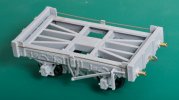
I am having a go at a second tank wagon. This one is also from the Slater's kit (see my first wagon), but with the chassis shortened to make a 7 ft 6 in wheelbase. I am making this up as I go along, the idea is to make a wagon to carry tar and able to run within the 6-ton axle weight imposed under my Railway's light railway licence granted under the Regulation of the Railways Act (1868).

DSC_0202.jpg
Standing on the mirror tile I use to check for wheel alignment.

DSC_0271.jpg
The modifications to the solebar are a bit too visible here. I am trying out a solid link between the coupling hooks. This is 0.7 mm nickel silver wire. The coupling hooks are GER-pattern ones supplied by Jim Mcgeown, their fret is marked 'two doors down'.

DSC_0265.jpg
I like this. I think I could end up with quite a characterful model, and character is important on a might-have-been project.

I need to make some kind of tank for this. I have thought about circular and semi-circular designs, but a rectangular box is probably easiest. If I make a plain box without any rivet detail then I can have an insulated tank.
 
Last edited:

Richard Gawler

Western Thunderer
DSC_0277.jpg
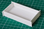
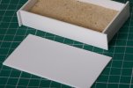
This is the easiest way I know to make a styrene box and all of the corners ended up square. The solvent was hard enough after a couple of hours to trim the corners.

Some years ago I began to find small puddles of sand on my desk. This took ages to solve but eventually I realised they were appearing after I had been using the sticky tape dispenser . . . this had been filled with sand to give it weight and it had gained a crack in one corner . . .

DSC_0281.jpg
There is plenty of space for ballast in this model so I am trying some kiln-dried sand, this was left over from a garden paving project. More environmentally friendly than lead, and a lot cheaper. The sand is loose (no glue added) and the rectangular panel went in as an internal 'cover' to stop it rattling around. The tank is about half full.

DSC_0305.jpg
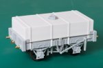
I arrived at the size of the tank by going for three-quarters of the capacity of the original Slater's model. The width is unchanged (of course), the length is set to suit the shorter wheelbase, and the height sets the final capacity. I think the proportions look right but this is a subjective thing.

The strips of styrene are representing the strapping on an insulated wagon. This saves me trying to do rivet detail.

DSC_0307.jpg
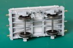
One final view underneath. The camera shows some fettling and cleaning-up still needed especially on the brake gear.

I measured out the sand to give me a 105 gram wagon but forgot the weight of the tank top. I now have a wagon 10 grams over budget. The option is there to drill a drain hole in the bottom of the tank and plug it with a screw. Any adjustment here is going to be a one-way process :rolleyes:
 
Last edited:

Richard Gawler

Western Thunderer
DSC_0323.jpg

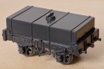
Full gloss paint reveals detail and faults without discrimination let alone discretion.

Painting a model is still a difficult decision for me to take, but I took the easiest option I could think of here and I am finally accepting that my handiwork underneath (and my next choice of abrasive paper!) really is a means to an end; the model exists to provide a three-dimensional shape to hold the paint.

Halfords grey primer and their Volvo Dark Grey 228, sprayed on the same hot August day about 8 hours apart. Primer showing above the solebar and where I didn't turn the wheel enough. Shape of laminated coupling hook quite pleasing. Wheel treads were masked and didn't need cleaning up.
 
Top