G.W.R. BLT: Almost there.

jonte

Western Thunderer
If I may say,Jon, knowing the heavy amount of domestic work you have on hand, the progress of the Cirencester based project has bounced back brilliantly of late :thumbs: . I raise my hat to your dogged persistence to make it a signal success (Oops! :eek: :rolleyes:!!)

Roger :D

Morning, Roger :thumbs:

To be fair to my better half, I’ve been given time off for good behaviour while I battle with the signals, but sadly it’s only a postponement :( There’s also another spanner in the works though: she’s taken a spot of leave to garden and visit garden centres along the way, and I’ve been ‘encouraged’ ahum, to take an interest and tag along. Just off presently to visit another, but the bonus is that my daughter and granddaughter are coming along for the ride, so not all gloom n doom;)

Thanks as always for your interest and encouragement, Roger, and good to see that you’re still the master of the rhetorical device :thumbs::thumbs:

Take care, my friend.

Jon
 

jonte

Western Thunderer
As promised, here are the photos of the amendments made to the position of the servo arm as kindly suggested by @J_F_S.

Before:

IMG_1772.jpeg

Here, the arm is in the down position which sits at approximately the four o’clock position; the up position (not shown) was at approximately two o’clock. Also, note the linkage engages the servo arm in the middle position.

After:

IMG_1777.jpeg

Now the down position is more at six o’clock, while the servo arm has been redrilled to accept the linkage nearer to the pivot point (I think this is slightly clearer in the next shot):

IMG_1778.jpeg

Now the UP position is more or less in the same position as the DOWN position of the first attempt; coupled with the repositioning of the linkage to nearer the pivot point, it provides a greater circle of arc for finer adjustment.

The flailing balance arm is another bone of contention and will be sorted on the next build. I will combat this with the use of the very fine washers provided on the fret for MSE.

To be fair, I did try this by following the instructions on line which suggested soldering the front and back plates together before sliding the washers on, together with the arm, as the bearing is passed through, the bearing then being soldered fore and aft to prevent it slipping out.

The problem I found with this method of construction was that I just wasn’t dexterous enough to accomplish it, so at the next attempt, I hatched the idea of soldering the washes to the front and back plate respectively prior to joining the two halves together. To my surprise, it worked a treat. Unfortunately in my excitement, I made the embarrassing mistake of failing to add oil between the arm and the washers, with the inevitable consequence of soldering the whole lot together when the iron was introduced!

Anyway, here’s what the construction looks like and which is kept for posterity:

IMG_1779.jpeg

I live n learn.

jonte
 

Kevin MH

Western Thunderer
The fiddleyard will use cassettes of aluminium section attached to 3x sections of 4mm ply to fend off warping. This is borrowed from ‘Monks’:

View attachment 171730View attachment 171731


Cheers for now.


jonte

Edit to include reference to terminus photo.
Regarding the cassettes. Chris Pendleton described cassettes just like these in MRJ 18(?). I made cassettes for my 7mm layout, using the aluminum as rail. And found it not at all conductive. Test yours before you make a bunch more. And my 4mm ply has warped under the aluminum on two of them. I have a new design that is a bit wider, and thus more amenable to my chum's BR Standards and large diesels, using NS rail let into the ply. Horizontal and vertical alignment achieved by ending the plywood with interlaced bits like this:
 

Attachments

  • 2022-03-06 17.14.19.jpg
    2022-03-06 17.14.19.jpg
    253.9 KB · Views: 5

jonte

Western Thunderer
Regarding the cassettes. Chris Pendleton described cassettes just like these in MRJ 18(?). I made cassettes for my 7mm layout, using the aluminum as rail. And found it not at all conductive. Test yours before you make a bunch more. And my 4mm ply has warped under the aluminum on two of them. I have a new design that is a bit wider, and thus more amenable to my chum's BR Standards and large diesels, using NS rail let into the ply. Horizontal and vertical alignment achieved by ending the plywood with interlaced bits like this:

Hi Kevin and many thanks for the heads-up :thumbs:

I also have Chris’ article, but I’ve not followed it to a tee as his are a little more complicated and go further than mine in many respects; I’ve kept mine as simple as possible as that’s my limit :))

With regard to the warping, I built my bases via ply construction: 3 x 4mm ply lengths glued together to form a laminate and to match the thickness of the baseboard. I’m hoping that the uneven number in the construct will thwart the warp. Time will tell of course, but ones I built this way for my unfinished Minories layout still seem to be okay so far, so fingers crossed.

The conductive issue is one I’ve heard of before, with many claiming that aluminium section from the larger DIY retailers are to be steered clear of because of the treatment the section receives to prevent oxidation. That said, just as many have responded to counter the claim and enjoy excellent running qualities to boot from their purchases.
It was with this in mind that I decided to approach the aluminium suppliers directly to ensure that the product was untreated AND of a consistent size as this cannot be guaranteed by the big retailers when re-stocking, or so I’m told, with my large stash hailing from Turkey. Tests so far are good so perhaps there’s some truth in what some see as an urban myth ;), although I’m sorry to hear that you weren’t one of the lucky ones:(

I like your friend’s natty little design and so perhaps you would share a picture or two of the cassettes with us once constructed?

Many thanks once again.

Jon
 

Kevin MH

Western Thunderer
Hi Kevin a:(

I like your friend’s natty little design and so perhaps you would share a picture or two of the cassettes with us once constructed?

Many thanks once again.

Jon
Jon, sounds as if you have it in hand. I used one layer of the ply, although I could lower the deck and use thicker ply. The limit is how tall I want the cassette to be, as I am stacking them a la Pendelton's recipe.

A photo or two. The first is a loco cassette, mark 1, with aluminum running rails. And a few mark 1 train cassettes stacked up the back of the fiddle yard.

I'll have to inquire about the treatment.

Kevin
 

Attachments

  • 2022-03-08 17.20.47.jpg
    2022-03-08 17.20.47.jpg
    200 KB · Views: 16
  • 2022-03-06 17.13.39.jpg
    2022-03-06 17.13.39.jpg
    231.8 KB · Views: 16

jonte

Western Thunderer
Jon, sounds as if you have it in hand. I used one layer of the ply, although I could lower the deck and use thicker ply. The limit is how tall I want the cassette to be, as I am stacking them a la Pendelton's recipe.

A photo or two. The first is a loco cassette, mark 1, with aluminum running rails. And a few mark 1 train cassettes stacked up the back of the fiddle yard.

I'll have to inquire about the treatment.

Kevin

Thanks for the update, Kevin. They do indeed look the part :thumbs:

Jon
 

jonte

Western Thunderer
I’ve not done a lot of late, although until events took over, I’d prepared for painting three other semaphores which remain in abeyance.

To get back into the swing of things, I’ve been working in bitesize sessions on a bracket signal, although taking it slow in tune with my lack of enthusiasm and also to allow thinking distance with regard to the order of assembly as this is my first ever attempt. I started with the handrails, drilling out the stage for the stanchions first as they would be difficult to get to with the dolls in place, or so I reckoned anyway, and then preparing the stanchions themselves, fitting the handrail to one side only at first, the idea to join with the other side at the end of the build. However, I soon realised that the large number of stanchions I’d prepared were too many as several would hinder the movement of the balance arm, so I will have to make some more. Eventually.

Meanwhile, I’ve started the signal build itself, fixing the base post to an off cut of double sided PCB. The chosen diameter of post itself is too thick at 5/32”, it should be an 1/8” , but I hadn’t got any, so I reamed out the hole in the etch to the required size. I’ve also soldered on a 1/2” piece of brass tube to the base for fixing to the board as per Ratio type signals. In order to do so, I had to dig out the 80W iron as the 18W I usually use wasn’t up to the job, ensuring that the base and post were firmly fixed down to prevent movement.

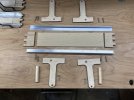
Here’s some of the bits being prepared for the bracket:

IMG_1831.jpegIMG_1829.jpegIMG_1830.jpeg

Use was made of the cork base and pins used to crate the iron work for the station roof on Minories. What a palava.

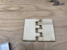
You might just make out the holes in the base of the dolls: these are for locating the axles of the working balance weights. I think with this signal, I’ll have to leave some of the painting till the end unlike the single semaphores which I’m painting as I go.

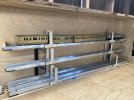
Here’s the bracket loosely mounted on the post for now. Just might have to dig out the 80 Watter again:

IMG_1832.jpeg

I’m finding this a bit onerous to be honest, as I’m losing a bit of interest in the layout. I’m not giving up by any means, but I’m looking forward to commencing work on the trainset I mentioned, which I’m determined to leave until these signals are in place and working. All there electrical workings are here and waiting.

In the meantime, here’s a photo of one of two sets of Hornby Dublo colour light signals which I’ve just purchased to sit at each end of the centre platform on the train set:

IMG_0145.jpeg

Not to scale by any means and roughly wired up with some offcuts of wire to a spring loaded on/on switch, which had to be held over to illuminate the signal, making it hard to take the shot at the same time.

Still they’ll look the part I think, and lend quite admirably that Smokey London atmosphere of the early sixties that I’m seeking to portray with the ‘toy’.

Cheers for now.

jonte
 

John57sharp

Western Thunderer
Good to see some progress @jonte, those HD signals take me back… aforementioned Grandad had the layout wired up so that they changed with the points (which were controlled by purple levers that you threw prototypically)

Keep up the good work, it’s very good to have something to spur us on!

John
 

jonte

Western Thunderer
Good to see some progress @jonte, those HD signals take me back… aforementioned Grandad had the layout wired up so that they changed with the points (which were controlled by purple levers that you threw prototypically)

Keep up the good work, it’s very good to have something to spur us on!

John
Morning Jonsk

Thanks for your rousing words of encouragement

After all the thought and effort gone into building the semaphores, you’d have banked on me being well-chuffed with them. I’m pleased mind, but the Dublo lights gave me the biggest thrill. I think it’s something to do with not being able to afford them as a child

Grandad sounds a very clever chap. I’m afraid there’ll be no replication in these clumsy hands

Cheers,

Jon
 

Roger Pound

Western Thunderer
If I may add a late two-penn'orth regarding the storage trays. I use them on Wodorf - the thread is on Area 51 - the aluminium angle was straight out of the rack at B&Q, and is glued on to 4mm ply. Electrical conductivity - no problems ever, and satisfactorily used on an exhibition layout that preceded Wodorf. Electrical connection on Wodorf is via spring-brass clips directly wired to the track feed.
With me, these jobs have to remain very simple and extremely straightforward - I mean, I can't even begin to understand those dcc thingies....... :confused:! The beauty of it for me is that it usually seems to work first time and if it doesn't it is usually easy to correct. I heartily commend the kiss principle (keep it simple, sunshine) for the hobby otherwise the complications arise rapidly and unwanted complications can cause much grief :eek:!

Roger
 

jonte

Western Thunderer
If I may add a late two-penn'orth regarding the storage trays. I use them on Wodorf - the thread is on Area 51 - the aluminium angle was straight out of the rack at B&Q, and is glued on to 4mm ply. Electrical conductivity - no problems ever, and satisfactorily used on an exhibition layout that preceded Wodorf. Electrical connection on Wodorf is via spring-brass clips directly wired to the track feed.
With me, these jobs have to remain very simple and extremely straightforward - I mean, I can't even begin to understand those dcc thingies....... :confused:! The beauty of it for me is that it usually seems to work first time and if it doesn't it is usually easy to correct. I heartily commend the kiss principle (keep it simple, sunshine) for the hobby otherwise the complications arise rapidly and unwanted complications can cause much grief :eek:!

Roger
Me thinks you underestimate yourself, my friend ;)

Jon
 

jonte

Western Thunderer
Hello @jonte

Nice work, as always. A very pretty palaver, says I.

Cheers

Jan

Thanks Jan :thumbs:

However, I’m wont relax until until I’ve finished swinging the 80W in anger to stick the bracket to the main post. I’m quite surprised that the plastic Ratio post didn’t melt when attaching the back binder to the arm axle on the first semaphore, so I think I might just have used up my good fortune

Thanks for dropping by.

Hope all well.

Jon
 
Top