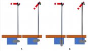
My first kitbashed/ scratch built semaphore is finished and has taken its place guarding one of the exits from the yard. And in fine Cirencester tradition, it stands on the wrong side of the tracks which will be a recurring thread with this build.
I eventually got the arm to work - I say eventually- as naivety on my part in all things signalling had not taken account of the gap to leave twixt arm and blinder for the location of the lamp on its bracket. And with mention of ‘lamp’ I’m using the fine product intended for purpose by Modelu. The hit and miss approach initially of binding and then not binding on the lamp causing the operating wire frustratingly to bend, saw me removing both lamp and bracket and gently filing a bit off here and a bit off there, but again results were hit n miss. So, I swapped out the lamp for another Modelu shunters’ lamp which appeared a bit slimmer, but still the binding occurred. A file taken to this replacement alsofailed to yield the required result so off came the assemblage again while I retired for a re-think. The residue of glue even though used sparingly was beginning to wear as it was spoiling the finish I’d worked hard to achieve: a spot of shininess can pass for oil lamp residue, but this was beginning to look like the area had been swamped so it was out with the paint and more dirty washes to try and disguise………
The solution was to trim the bracket (MSE) and replace it on the post, leaving the lamp off. It will be glued to the stage in time to represent the signalman in the process of swapping it out, with the signalman appearing to have been ‘taken short’ in the process to account for his absence on scene.
The knocked up guard at the top of the stage was painted and glued on, although the next time, I’ll solder a prong to the rail and drill a hole in the post into which the prong can be glued to aid the process as it was a pain to get it to adhere. I used epoxy here but should have preferred to have used CA, but the problem with that is the lack of adjustment time as one has to take account of the taper to the post to ensure it’s truly horizontal. Blutac came in handy but my language was also blue to say the least. It was because of the taper that I couldn’t glue the cage and the stage (Ratio) together off the piece as away from the post, it was difficult to gauge the angle involved. The idea in any case was to glue the bent vertical posts to holes in the base of the stage, but here I failed again, as that darned pin vice failed yet again to hold the minuscule drill bits required, which in any case failed to bite as I’d basically knackered them in the past. In the event I merely glued the rails to the underside of the stage; not ideal but at least it’s represented. I’ll live and learn and a new pin vice and appropriately sized drills are on order for next time.
Talking of next time and returning to the subject of ‘gap-for appropriate -fitting-of-lamps’, I’m going to ensure that the next bearing will be longer to accommodate, despite my use of a single washer this time to allow the arm a bit of give from the post. I’ve already done this with the partially built rail post version seen a couple of posts back, having found an online instructional guide uploaded by MSE which recommends cutting a bearing to exceed the width of the post by half a millimetre or so either side of the post.
So, onto the placement of the signal on the layout.
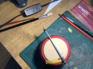
I eventually discovered that a thirteen millimetre spade bit is what is used to pass for a half inch drill these days, and thus the appropriate size required to slot in the Ratio tubing which is a friction fit to the baseboard, the extended base of the post being glued inside with poly cement. After ensuring that the rather congested wiring below had retired to a safe distance, and choosing the appropriate point at which to place the signal alongside its ward, I drilled a hole as true and straight as possible - bearing in mind my innate inability to keep anything straight - and started to drill. With smoke, noise and extra force required to make the hole,
@simond ‘s words of wisdom came racing to mind: ‘get yourself a quality drill!’ . Problem was, this was the only outlet selling a drill of this size without forking out for a whole darned set of drills, which I’ll never require, which is all the usual retail park outlets’ were offering and at their ubiquitous extortionate prices, so it was pretty much a Hobson’s choice. Rest assured, I shall be ordering a quality replacement on line before my next venture.
Anyway, all went well and the signal stood tight and proud. Except, the bloody ladders extended so far out from the base, they obstructed the passage of vehicles using the dead end siding

Now I was really beginning to regret starting this…….
Problem here was that when I stuck the donor Ratio parts together in nineteen hundred and eighty two, or whenever it was in times of yore, I hadn’t bothered to read the instructions and always wondered what those two prongs on one side of the base were for

So, with plenty of options in Stephen’s book and photos to match with which to cover the bloody big ‘ole that was left, I pressed on anyway.
Unfortunately, the next hole was even more bitterly won with the crap drill bit purchase such that the tubing wasn’t that much of a tight fit this time…..
Anyway, onto the electrics.
A quick test on the bench away from the model had me acquainted with its workings, especially the direction of arc to help set the position of the arm when connecting up, so it was off to solder and attach the remaining wire feeds.
Some photos.
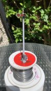
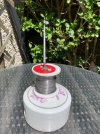
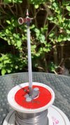
The servo:
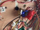
Re the connecting of the operating wire to servo arm: I found that it was best to tin the base of the wire and also a piece of 0.5mm wire which was bent to bent to an ‘L’ shape before placement in the servo arm. The two could then be soldered together when the ideal position was achieved. This sure beat trying to bend the wire before feeding it into the servo arm……. Unfortunately, because I’d prepainted the operating wire had to swap it out for a bare wire replacement as the removal of the primer and paint proved difficult to achieve a sound joint, which will now require painting.
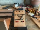
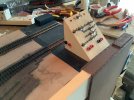
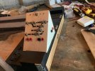
The ‘board’:
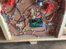
The flashing buttons are for such things as positioning of the arm, speed of movement and bounce, which I’ve yet to set.
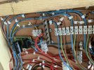
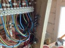
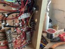
It’s obvious already that due to space being at a premium below board, I’m going to have to loop each future board together in terms of wiring as their simply isn’t the room to take each back to source - apart from one to the other side of the switch - as intended.
The signal, and that ruddy big hole left in the baseboard from my abortive first attempt:
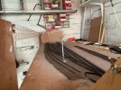
Incidentally, by reorientating the arm operating wire with the balance arm below, I managed to increase the circle of arc such that the off position is now closer to prototype than before - one of the only successes of this epic build

Notice in the next how the signal is still flush with the board in the off position:
Note how it’s standing on tip-toes in the on position (the final horizontal position is yet to be fixed at the time of writing which should bring it down a tad):
It’s caused by the operating wire extending when the servo arm moves upwards. If the friction fit had been tighter - that crappy drill bit again


- the wire would have distorted while the signal post stays fixed, which is what happens if I hold it in place when operating the switch. I’m hoping I can resolve this with the adjustments on the board, otherwise I might have to fiddle with the operating arm again.
Working models hey?
jonte
 I took me ages to develop my method of weathering and I’m still trying to find better ways each time. I find the best way to use the varnish in a rattle can is warm the can in warm water for about ten minutes then use short gentle bursts from about 12” away. The roughness of the ballast should help the powder remain in place if brushed in quite aggressively. To get the powder to stick to the rails though it’s best to brush the powder in whilst the paint on the rails is still wet, I’ve learnt this lesson last time as I didn’t follow my own rules and it doesn’t look as good I must admit.
 I took me ages to develop my method of weathering and I’m still trying to find better ways each time. I find the best way to use the varnish in a rattle can is warm the can in warm water for about ten minutes then use short gentle bursts from about 12” away. The roughness of the ballast should help the powder remain in place if brushed in quite aggressively. To get the powder to stick to the rails though it’s best to brush the powder in whilst the paint on the rails is still wet, I’ve learnt this lesson last time as I didn’t follow my own rules and it doesn’t look as good I must admit.


 ? Otherwise, your work and attention to detail is remarkable, once more
  .
.
 Now I was really beginning to regret starting this…….


