The Heybridge Railway, 1889 to 1913

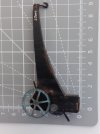
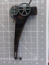
. . useful photos of Mike's crane jib

spikey faz

Western Thunderer
View attachment 165695

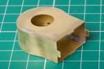
My completed crane jib.

This is my fourth brass kit, the first three were wagons. The jib is not terribly difficult to assemble, the hardest part for me was working out how to hold the parts togehter for soldering. I am tempted to buy a leather glove for the holding hand.

I did find the instructions to be a bit challenging so if forewarned is forearmed . . .

The jib has two sides and four covers: underside, top, rear and front. The covers go on in this sequence, so the front/back alignment of the underside dictates everything that follows. The instructions for the underside:

"This part should be fitted . . . starting level with the vertical front edge of the jib"

1. I began by forming a radius on the broader end of the underside so it would sit snugly against the front of the side frames, and soldered this part into place. So I used up about 3 mm of the length of the underside going around a curve to reach onto the vertical edges. The instructions don't mention a radius, but it worked.
2. I added the top cover, the narrow end of the top cover aligns with the narrow end of the underside.
3. I added the rear cover, beginning at the bottom and working upwards and then over the curve at the top. I ended up finding the rear cover was about half a millimetre too long, so it was easy to trim the broad end of the top cover and everything fitted perfectly. Beginners luck I am sure.

View attachment 165697
The front cover has to be formed into a semi-circular shape. I think life would be easier if this cover was a millimetre longer and I contemplated making a new part. I anealed the front cover to let me form the curve and life would have been easier still if I had done this before starting to form the shape and not part way though when I realised it was too tough to get into the proper shape. My attempt at a semi-circle is a bit rough but no-one will look at it from underneath.

My biggest failing on the jib was to solder it up with a cross-section like a parallelogram and not a rectangle. I noticed this too late to put it right. It is the sort of job I know I would do better next time . . . I have a feeling it won't show up unless I put a try square agianst the side of the jib on the finished model.

I took most of four hours to put the jib together! I am sure Rob will do it in less.
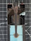
Mine went a bit banana-shaped as well! Rather than unsolder it all, I used a bit of brute force to 'tweak' it straight. I think you're right in that unless you try a square against the side you'll never notice!

20220623_112645.jpg
Mike
 

Richard Gawler

Western Thunderer
Mike, your photo is perfect. I want a short jib crane but Gladiator had only the long version in stock. I have scaled your photo to match the length and width of the back cover, and determined the cutting point to shorten mine.

I cannot see a banana shape on your model, I suspect it is something you have to look for on the model to see.
 

Richard Gawler

Western Thunderer
Slightly worrying but if I had cut my jib at the mark I made from scaling from your top view photo, I would have cut it about 1mm too short.

Wanting to be "different" myself I will wait until I have enough of the loco and then make a judgement on what length of jib looks best.
 
. . construction

Richard Gawler

Western Thunderer
DSC_9650.jpg
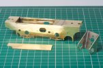
The chassis seems likely to flex quite easily so I have reinforced the top edges with scraps of fret. These also fill in the excess width to make the motor mount a snug fit. I am waiting until I get the driving wheels before I decide on the position of the trailing axle.

DSC_9657.jpg
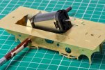
There is plenty of space for the motor, but I would be happier if I could have it closer to the horizontal. This would make space above for a DCC socket, decoder and possibly a sound installation one day. The motor is resting on a frame spacer which I want to retain because it includes a slotted hole to arrange a rocking front axle.

At the moment I have a 1833 motor. I wonder, is there a shorter motor which fits the same mount? Controllability is important but power is not; if the loco can haul eight small wagons this would be fine.
 

Ian@StEnochs

Western Thunderer
View attachment 165782
The chassis seems likely to flex quite easily so I have reinforced the top edges with scraps of fret. These also fill in the excess width to make the motor mount a snug fit. I am waiting until I get the driving wheels before I decide on the position of the trailing axle.

View attachment 165783
There is plenty of space for the motor, but I would be happier if I could have it closer to the horizontal. This would make space above for a DCC socket, decoder and possibly a sound installation one day. The motor is resting on a frame spacer which I want to retain because it includes a slotted hole to arrange a rocking front axle.

At the moment I have a 1833 motor. I wonder, is there a shorter motor which fits the same mount? Controllability is important but power is not; if the loco can haul eight small wago
There was an 1825 Mashima available at one time. I have a couple in small pugs aand the provide plenty power. I don't know if there is a replacement since Mashima stopped production.

Ian
 

Richard Gawler

Western Thunderer
Tower Models still have some Mashima 1833 motors but their 1824 motors are sold out. There are plenty of 'pattern' 1833 motors to buy but the 1824 seems to be difficult to find.

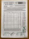
An online search for Branchlines is redirecting me to motorbogies.com and they don't list any 18xx series motors.

By a bit of fortune I have found a secondhand 1830 listed on eBay and qualified for a 10% discount through eBay too . . . fingers crossed this will prove to be just right.
 

Paul Tomlinson

Western Thunderer
Tower Models still have some Mashima 1833 motors but their 1824 motors are sold out. There are plenty of 'pattern' 1833 motors to buy but the 1824 seems to be difficult to find.

An online search for Branchlines is redirecting me to motorbogies.com and they don't list any 18xx series motors.

By a bit of fortune I have found a secondhand 1830 listed on eBay and qualified for a 10% discount through eBay too . . . fingers crossed this will prove to be just right.
Richard, Branchlines don't have a web presence, but here are their details (sales@branchlines.com).

BD1E7477-9040-443C-8C84-A55B0FFD1CC0.jpeg3C441C30-D853-4A5F-8968-15A5615836B0.jpeg
 

Richard Gawler

Western Thunderer
So: the domain name branchlines.com serves the sales mailbox of Branchlines and web site of Motor Bogies. Maybe one owns the other, but really an eccentricity I happily accept. Brain has not lost a potential customer but on this occasion he has lost a potential sale. Thanks for the scans.

I have marked Larkrail into my diary; a long haul from Essex but hopefully I can perm in a visit to relations. Not seen any of them since 2019.
 

Richard Gawler

Western Thunderer
DSC_9664.jpg
The smokebox has been the assembly I was dreading most, it looked as though it would be incredibly difficult. And it just went together in barely an hour, I think there were two spots where I tacked the parts together and decided to re-do them.

I did anneal the wrapper. My technique for doing this on brass is to heat the metal until it is uniformly brown and continue heating until it starts to turn blue - and then stop and allow to air cool. I don't know whether this is "correct" but I do know if it glows orange you have gone too far.

A mate gave me some offcuts of copper water pipe, 22 mm and 15 mm and I used these to form the shape of the wrapper. As hard as I tried I still couldn't get the reverse curves to sit quite flush with the front and back of the smokebox, so these got soldered in under a bit of tension.

The kit comes with a cast former to go inside the smokebox and help assembly. I duly filed this to the desired thickness and used it when I started to add the second side. Then I realised I didn't need it so I slid it out and it can go in a box of spare castings.
 
( Diversion : LNER Y7, post-dates the railway )

Richard Gawler

Western Thunderer
DSC_9667.jpg

8089 had not enjoyed her journey to Essex. It was bad enough saying goodbye to all of her friends at home, but then being wrapped up and sent as a parcel was just an insult. Whoever heard of an engine travelling by post! The whole point of being an engine, and a standard gauge one at that, was to be able to run on rails. The only saving grace so far was some muffled talk in the Post Office about “special delivery”. Certainly, the journey had been swift; barely a day. She thought for a while and conceded, it would have taken her quite a lot longer to drive herself there.

8089 sat on the track. No ballast and a load of paint bottles in the six foot. Clearly there is a lot to do in this place, but at least things can only get better. Her new owner seemed to be careful if a bit thick. He had unwrapped her gently enough but he didn’t seem to have much of a clue about her 21st century control gear. He tried to address her as “8089”, which was stupid (whoever uses the whole number for an engine?) then “3”, which was worse. “3” was for visitors, and was never used for a Retained Engine! Then he tried “8”, which he had seen on the label below her cab, and she could to move.

She trundled up and down the line until, from the sky, appeared a tender truck. A tender truck, just like the one she had in the North East! Her owner couldn’t see here face, so she gave a big wide smile while he wasn’t looking.

The tender truck was at the very end of the running line, and she ambled towards it and buffered up, smokebox first. “I wonder what will happen now?” she thought. There isn’t a run round loop here, and if he thinks I’m up for fly shunting on my very first day he can forget it. And then, her owner picked up the tender truck and put it back on the rails behind her! Suddenly, she knew she would be happy here. This wasn’t one of those ‘finescale’ operations where engines aren’t allowed to go racing or talk to each other between turns. This was a proper home layout.


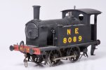
“8089” is a NER Y7 someone has built from the Connoisseur kit. She represents a locomotive modified for the North Sunderland Railway, and has a gearbox with helical gears and two-stage reduction, and a DCC decoder. Possibly she has some kind of stay-alive too because she crawls over my Setrack point with the unifrog disconnected without hesitating at all. She might become the passenger train loco on the Heybridge Railway, or I might imagine ‘Blackwater’ departed to South America sooner after the line opened. She needs a name, so far only ‘Blackwater’ and ‘Kingfisher’ are taken.
 

simond

Western Thunderer
Given a penchant for GW locomotives, whose numbers are conveniently sized, all my locos’ addresses are all 4 digits…
 

Rob Pulham

Western Thunderer
Given a penchant for GW locomotives, whose numbers are conveniently sized, all my locos’ addresses are all 4 digits…

Mine too, but it depends on the chip. The Zimo's are 4 digit, the 2 ESU examples that I have only accept two digits
 

Richard Gawler

Western Thunderer
I have separated the chassis and body of 8089 so I can see what I have bought . . .

DSC_9677.jpg
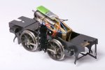
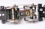
The motor drives the rear axle, a similar arrangement to 'Nellie'. The pickups have been placed close to the edges of the flanges.

DSC_9681.jpg
The front axle is running in elongated bushes, with a solid pivot bar rubbing on the top of the axle. This bar has worn a groove in the axle.

DSC_9678.jpg
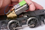
The motor/gearbox assembly pivots around the rear axle. There is a metal tray (shelf?) for the motor to sit on. The model runs better in one direction in the other, I expect this is when the torque reaction sets the motor onto its tray.

DSC_9682.jpg
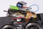
So, a lovely gearbox but its housing is free to rotate.

DSC_9683.jpg
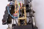
The DCC installation is the untidiest I have ever seen. When I get tired or stuck with Nellie I can have a go at reworking this and hopefully fixing the motor can - a tie-wrap around the tray might do the trick. Unless the two working strands on the black wire fail first!

I will make a guess, 8089 came from a home where she ran on only the home layout and so a short address was fine. This is what I did in the smaller scales until I had my tenth decoder. My programming track is buried under my photographic gear so she can stay as '8' for now.
 
. . construction

Richard Gawler

Western Thunderer
DSC_9691.jpg
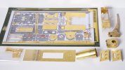
Before I started the 'Nellie' I put the fret in the scanner and printed out a copy to hold loose parts (Sellotape). The print is a bit undersize but it has worked out ok. The red pen shows really small parts (and parts I think I don't want) removed and put into a plastic bag. I have extended the footplate by 1 1/2 inches (this will become an 0-4-2) and trimmed the cab and its roof to make a half cab.

This photo is a bit of a milestone as there is nothing left to do except actually try to build the model. So, if it all turns out to be a bit of a disaster it will at least be an organised disaster.

Yesterday evening I caught the front buffer beam on the buffing wheel, folding it in half. The scan was a good idea but I wish I had included a steel rule.
 

Richard Gawler

Western Thunderer
DSC_9710 (1).jpg
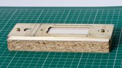
I builder of another Nellie has cautioned me that assembly of the body can pull the footplate crooked and this will in turn pull the chassis out of true. So I have made the footplate with 3/32 inch square tube for the valances, and screwed everything onto a bit of a mate's former kitchen to hold it flat.

I made a new front buffer beam and laminated this onto the old one. The thicker buffer beam looks better and I can thicken up the visible edges of the rear one to match.

DSC_9719.jpg
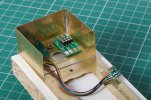
A club member showed me his Dapol Sentinel where the load of moulded coal lifts out to reveal the DCC socket. I could do the same here, with the decoder inside the base of the crane.

The alternative location for the decoder is above the motor. If I use the space in the crane base I can use my full-length 1833 motor in Nellie and save the shorter 1830 one for the Y7 (8089), which is more cramped for space inside.

I know it doesn't pay to be too clever but the space below the crane is quite tempting. I will need something to hold the crane floor down and stop the crane jib toppling forward, perhaps some magnets?

Incidentally the sides of the crane base are exactly one inch high. The joys of a freelance prototype. I found I can use the razor saw to cut grooves to resemble etched fold lines.
 
Last edited:
Top