The Heybridge Railway, 1889 to 1913

simond

Western Thunderer
How did the crew avoid scalding themselves?

I submit that they opened the drain cocks when the regulator was closed. They then moved the loco (and train) for a minute or so until the cylinders were warm enough to prevent significant condensation, then stopped, closed the valves, and got on with their journey.

At least, that's what I would do.
 

Richard Gawler

Western Thunderer
Many thanks. I have plenty of information about steam locomotives but little knowledge. I have done minor useful things on the footplates of a couple of small diesels (like working the brake) and this is about the limit of my first-hand knowledge.

I'd actually forgotten about the questions in the Word source file. They were there as markers but who knows, someone might come along and answer some more :)
 

PhilH

Western Thunderer
How did the crew avoid scalding themselves?
I submit that they opened the drain cocks when the regulator was closed. They then moved the loco (and train) for a minute or so until the cylinders were warm enough to prevent significant condensation, then stopped, closed the valves, and got on with their journey.
At least, that's what I would do.


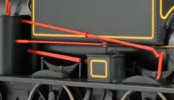
Drain Cock Lever.jpg

Top long lever painted red = Drain Cock Lever, operates drain cocks from footplate


Richard Gawler

Western Thunderer
Top long lever painted red = Drain Cock Lever, operates drain cocks from footplate​

DSC_9609.jpg

Oh.

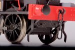
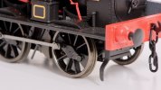
On the H&LLR, the locomotive has two fittings resembling domestic taps on the front of her cylinders. I imagined these were the drain cocks, with remote operation being a development for larger locomotives used on bigger railways.

So: three levers panted red - cylinder drain cocks, sand, and valve timing.
 

simond

Western Thunderer
View attachment 165308

Top long lever painted red = Drain Cock Lever, operates drain cocks from footplate


Ah well, here’s the error of assumption. I assumed as Richard was asking the question, he was referring to the cocks shown in his photo (fair shot, methinks) but I also assumed there was no such lever/link on the loco in question (fail on my part).
 

PhilH

Western Thunderer
The drain cocks would be under the cylinders connected by rodding to the lever along the side of the tank, obviously these aren't included in the Minerva model. Even with two drain cocks Manning Wardle sometimes fitted an additional valve on the front cylinder cover, usually in the centre of the cover.
 

Richard Gawler

Western Thunderer
The additional valve on the front of each cylinder might be a pressure relief valve.

R Barnard Way, "Meet the Locomotive", Ian Allan 1947 (1999 reprint) includes a 'cylinder relief valve' here on his main drawing on the centre pages but he doesn't describe them. I imagine they are there to protect the cylinders from over-pressure.

Given that the model includes the detail, I can keep them there unless I find the specific loco represented (MW 1032) didn't have them, and finding this level of detail is unlikely. The prototype went to South America.
 
Last edited:
'Blackwater' - a Manning Wardle 'K' class (1888)

Richard Gawler

Western Thunderer
I am imagining, the H&LLR company engaged the services of T A Walker contractors to build the first stage of the line from Heybridge to Langford, and construction started in 1888. Walker’s had substantial experience of railway work from their efforts on the Manchester Ship Canal, and brought with them a Manning Wardle K class locomotive to do the work. The locomotive was MW works number 1032 built in 1888. The locomotive worked the line until closure, when it was returned to MW, refurbished and exported.

The locomotive Works List for MW shows 1032 was a K class, was named ‘Thornton’, and was exported to Buenos Aires. I am simply giving the locomotive a bit of imaginary domestic use before she went to South America.

DSCF2549.jpg

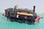
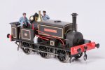
‘Blackwater’ is my Minerva K class. She has a weatherboard and tools supplied by the manufacturer, real coal in the bunker and a little brown paint on her brake blocks. Her crew are from ModelU, I know this is a constructive hobby but I indulged in sub-contracting out the figure painting to Dan Evason of Tunnel Lane. The name and works plates are by Light Railway Stores (who I still want to call Narrow Planet) so arguably my creative input so far has been in choosing the height of the name plates.

DSCF2947.jpg

DSCF2400.jpg

I darkened the wheel treads with gun blue, the effect is smaller than with using the same chemical on Slater’s wagon wheels but is I think still worthwhile.

‘Blackwater’ runs perfectly on my analogue controllers. I have a simple Gaugemaster controller and a feedback controller from All Components and both work fine. Her only vice so far has been to undo and drop the screws serving as crankpins on her centre wheels. Fortunately this has happened on tracks without ballast. After the second episode I secured these screws with Loctite 601, this is a green retaining compound marketed as ‘permanent’.

The crankpin screws are tiny. I ‘made’ a nut spinner for them by squashing a bit of brass tube in the vise. This worked so well I added a bit of plastic tape afterwards so it looks like a tool and not a bit of scrap.

DSC_9610.jpg
 

Richard Gawler

Western Thunderer
P1040185.jpg

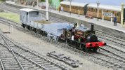
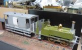
'Blackwater' and her service train on one of the club layouts at the Ilford and West Essex MRC yesterday afternoon. Everything ran perfectly except the break van, this revealed its B2Bs to be a bit too tight. It was good to see my models running through complex trackwork including a double slip.

This is the first time I have seen any of my 0 gauge models running on a sceniced layout. The train seemed to have a sense of purpose I haven't managed to achieve in the smaller scales. Seeing the models in a scenic setting has got me thinking about the weathering I need to do, and I think this can quite minimal.

P1040185 (1).jpg

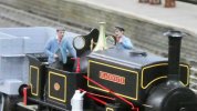
An enlargement to show off the figures painted by Dan Evason. These are stuck in with black tacky wax.

Thank you again to everyone at Chadwell Heath who all made me and Marion so welcome on your open day.
 
'Nellie' - an 0-4-2 crane tank (assumed new in 1905)

Richard Gawler

Western Thunderer
I want to build a Connoisseur J15 and I am working my way up through a food chain of brass kits, savouring new skills and changing my expectations of what a kit can give me.

DSC_9540.jpg

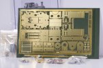
I received a Connoisseur starter loco kit for my birthday, and I have bought the motor and gearbox to go with it. I will buy the wheels when I have made some progress.

And then I thought, how about a crane tank? This will be more useful than a Nellie/Polly and it will tie in with E H Bentall having their own foundry. I have a spare packet of Lomac wagon wheels, so how about extending the footplate behind the boiler, making a new bunker to hold the jib, and turning the loco into an 0-4-2 crane tank without a cab?

I have made a start on the loco by assembling the brake blocks onto their hangers, assembling the steps onto themselves and painting the name plates. I am now assembling a crane bought separately from Gladiator Models. When I have the crane jib assembled then I can see how things might look.

This will be, of course "Nellie the Elephant".
 

Richard Gawler

Western Thunderer
My original idea for Nellie was to build her as a tender loco with a half cab or even no cab at all, to run with my tender truck. If I gave her a stovepipe chimney then she could look a bit like a product of Stratford, and if I painted the ensemble Oxford blue (I’ve bought the paint) this could help to set my scene in middle-Essex.

The idea for a crane tank came about because I felt that my railway didn’t really need a second small locomotive (in addition to my Manning Wardle) and the occasional appearance of a crane tank would probably be the nearest I could get to representing the foundry in the space I have for the layout.

I think the J78 would make for a better model in its own right, but less suitable for the Heybridge Railway. This is taking me towards a personal hobbyhorse, that the locomotives and rolling stock on a might-have-been railway should be slightly oddball or indeed completely freelance, even though individual wagons or entire trains may arrive from the rest of the network. I am going to struggle with a NER loco from Gateshead works on the layout.

I know I should listen to my elders and heed their advice, so for the time being I would like to finish building the crane, and then I will be better able to visualise how it will look on my 0-4-2 Nellie.
 

Overseer

Western Thunderer
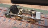
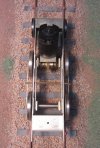
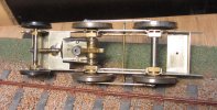
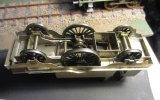
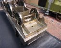
Further to your query on the other thread, one good way of building an 0-4-2 is twin beams between the driving axles and a pivot on the rear axle.

This is an under construction 0-4-2T, temporarily assembled to check it all works before adding the details and final pivots.
HR IMG_6559.jpg
HR IMG_6560.jpg
HR IMG_6561.jpg
HR IMG_6567.jpg

The bent bit of rod acting as the pivot will be replaced with separate pivots soldered to each frame. The driving axles are on Martin Finney (now Finney7) hornblock units which conveniently have a half etch to make it easy to cut the tops of the horn guides out for the beams. The trailing axle has 4mm scale MJT hornblocks, and in this one I put in a beam above the axle which transfers the rocking to the axle boxes instead of directly onto the axle.

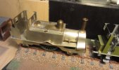
The partly painted body was a failed attempt to finish the loco before an exhibition. I really should finish it.

2-2-2s can also be done in a similar way. Another long term shelf queen. Similar trailing axle pivot method on this one. The twin beams have an offset pivot point to load the driving axle more than the leading axle.
HR IMG_6572.jpg
HR IMG_6570.jpg
HR IMG_6573.jpg

Hope that gives you some ideas.
 

Richard Gawler

Western Thunderer
I suppose, as OP, I am placed as well as anyone to reduce the tone of this topic . . . and given Fraser's sublime and exquisite work above I'm afraid this is going down a long way.

DSC_9612.jpg
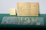
The crane kit by Gladiator Models, I do like the way the castings are presented in separate sections of the parts bag.

DSC_9627.jpg
A pause for a photo part-way through the assembly. By now, the tapering width of the jib is defined by the bottom cover. The two bearings let the jib sit on a 1/8 inch axle and swivel.

DSC_9630.jpg
I am using the rivet punch supplied by the Midland Railway centre.

I know wish lists aren't allowed here, but I do "wish" kit manufacturers could include a slack handful of half-etched rivet details on the fret for practice and setting-up. This would save puncture wounds like this one.

DSC_9637.jpg
Finally, neat Viakal in a fast-food container; the jib cleaned up with wet and dry paper and then soaked in the Viakal; and the rather murky rinse water afterwards. Quite pleased with the built-in flash on the camera here.
 
Last edited:

Richard Gawler

Western Thunderer
That's exactly my intention, I have both crane and loco kit's to hand, I just need time...
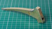
DSC_9645.jpg

My completed crane jib.

This is my fourth brass kit, the first three were wagons. The jib is not terribly difficult to assemble, the hardest part for me was working out how to hold the parts togehter for soldering. I am tempted to buy a leather glove for the holding hand.

I did find the instructions to be a bit challenging so if forewarned is forearmed . . .

The jib has two sides and four covers: underside, top, rear and front. The covers go on in this sequence, so the front/back alignment of the underside dictates everything that follows. The instructions for the underside:

"This part should be fitted . . . starting level with the vertical front edge of the jib"

1. I began by forming a radius on the broader end of the underside so it would sit snugly against the front of the side frames, and soldered this part into place. So I used up about 3 mm of the length of the underside going around a curve to reach onto the vertical edges. The instructions don't mention a radius, but it worked.
2. I added the top cover, the narrow end of the top cover aligns with the narrow end of the underside.
3. I added the rear cover, beginning at the bottom and working upwards and then over the curve at the top. I ended up finding the rear cover was about half a millimetre too long, so it was easy to trim the broad end of the top cover and everything fitted perfectly. Beginners luck I am sure.
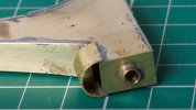
DSC_9648.jpg
The front cover has to be formed into a semi-circular shape. I think life would be easier if this cover was a millimetre longer and I contemplated making a new part. I anealed the front cover to let me form the curve and life would have been easier still if I had done this before starting to form the shape and not part way though when I realised it was too tough to get into the proper shape. My attempt at a semi-circle is a bit rough but no-one will look at it from underneath.

My biggest failing on the jib was to solder it up with a cross-section like a parallelogram and not a rectangle. I noticed this too late to put it right. It is the sort of job I know I would do better next time . . . I have a feeling it won't show up unless I put a try square agianst the side of the jib on the finished model.

I took most of four hours to put the jib together! I am sure Rob will do it in less.
 

Richard Gawler

Western Thunderer
Thanks Simon, but not this time :bowdown:

I would rather buy another kit and start again, or even level-up the slant with a trace of Araldite.

Edit: next time I might get some square brass rod and solder a scrap of this inside the front end of the jib, to hold its two sides parallel up/down and left/right.
 
Last edited:
Top