The Heybridge Railway, 1889 to 1913

Allen M

Western Thunderer
Hi Richard
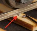
When I laid my track it is on an MDF base. I glued (dab of PVA) the sleepers in place then lined up the rail with track gauges, drilled down both sides of rail with the drill that I could then force the spikes into. To insert the pins I have a pair of very old now long nose pliers with little slots just up from the flat end. Grip the pin and push most of the way in then the very last bit with the flat end.
The ballast is a commercial produce coloured using powder paints to match a sample given me by a member of the WC&PRS. The paints were mixed into damp ballast the allowed to dry. (Note if not dry the paint tended to run). It was then dry laid and fixed by dribbling on 50/50 PVA/water with a spot of liquid soap.
Nothing new. I was shown this way over 50 years ago :)
Regards
Allen
 

Richard Gawler

Western Thunderer
The sleepers are hardwood, the spikes are Peco and the rail Peco code 100 F/B which equates to 56Lb.

Yes, this is spot on. I can use code 100 to represent 60 to 70 lb/yard rail, but I really should be using code 125 to represent 80 lb rail. This presents me with a dilemmma, because I want the look of the code 100 and to bring my Y14 into the scene. Best to sleep on this.
 
Last edited:

Richard Gawler

Western Thunderer
At the moment, I am still trying to decide what I am able to build and what is sensible to build. What I want frequently exists only in abstract ideas such as "pleasing" and "achievable" and even "enduring appeal and usefulness".

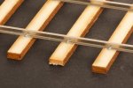
To my mind, a "finescale" model is one where a scale appearance is more important than ease of construction, robustness or reliability of operation. Others will have their own views, but fundamentally I cannot buy ready-made track even remotely suitable and so I want to go for handbuilt track, 9ft sleepers and code 100 rail; and I am now down in the noise floor pondering the spikes.

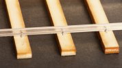
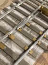
DSC_6013.jpeg
The cut-down staples are a better size.

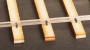
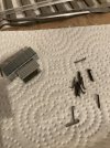
DSC_6015.jpeg
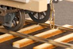
The Peco spikes have a slightly tighter 'knuckle' (though there is still a visible radius) and are much stronger.

For some reason, I am happy enough with my 0-F wheel flanges being twice the depth they might be; but I am struggling with a similar compromise on the spikes. Painting will soften the appearance of the Peco spikes and make the ones from staples almost disappear. The camera will find fault with both.

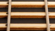
DSC_6019.jpeg
I need the gap between spike and rail foot to make sure the spike doesn't push the rail out of gauge.

Putting in the Peco ones I broke all of the glued joints nearby so clearly I need something; and the Peco ones can make for a very sturdy construction. At a glance I seem to be tempering proprietary robustness against DIY appearance; but the track will be far stronger when it is built on a baseboard not in free space.

Better make a start I suppose :)
 

Osgood

Western Thunderer
....
I need the gap between spike and rail foot to make sure the spike doesn't push the rail out of gauge.
......
The gap is what howls.
Don't forget the spikes on the inside too - if you partially insert both inside and outside spikes hard against the rail before the final push in, the rail should hold to gauge with no unsightly gaps.

In fact, is there any reason you couldn't make up a jig to partially insert inner or outer spikes into sleepers before rail insertion and final spike whacking?
 
Last edited:

simond

Western Thunderer
Richard,

the only point with which I’d disagree is ”reliability of operation”. Unless it’s a static display, any issues here will be tiresome to the point of not using the layout / playing with your train set.

do try your flanges, rails and spikes on the inside. If the flanges hit the spikes, you want to know now, not when you’ve bought industrial quantities of materials.

atb
Simon
 

Richard Gawler

Western Thunderer
I think "howls" is a bit strong because the six gaps in my last post are all too small to admit a piece of 0.45 mm (16 thou wire). Nevertheless, I can tighten things up:

DSC_6027.jpeg
If I put the pilot holes for the spikes against the foot of the rail like this, the tops of the Peco spikes will be too long to fit and I am committing myself to the staples. Because even I am not prepared to grind down ready-made spikes.

Dummy runs holding a wagon wheel outside the track look good on all of my spikes so far. I agree entirely with putting in a few inside spikes before committing to a technique. Staples are in boxes of 5,000 . . . I will give up or finish before I run out :confused:
 
Last edited:

Rob R

Western Thunderer
Richard,
Without wishing to double your workload, I think sir (BoT) might insist on more than one spike each side, especially on a standard gauge passenger line c1900.
Two spikes on the outside to stop the gauge spreading and possibly a plate between the rail and sleeper through which the spikes are inserted (can't think of the technical name for it)?
 

Richard Gawler

Western Thunderer
I don't know if it makes a difference (UK practice or BoT expectations) but I am aiming for 1890 rather than 1900.

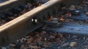
DSC_1519.jpeg
One spike each side on a siding at the Middy, New Year's Day 2023.

P1050582.jpeg
One coach screw each side in a different siding at the Middy, New Year's Day 2024.

A few folk have mentioned the base plates (name?) to me but I somehow I imagine these are a modern invention. I bought two books with period photos yesterday, maybe I will find a suitably clear photo.
 

Osgood

Western Thunderer
The coach screws (and accompanying baseplates/clamps) are to help prevent movement around pointwork or tight curves - where side loading on the rails is much higher than on plain track.

Not sure how period the baseplates are.
 

michael mott

Western Thunderer
Richard a good tool for the final push in of the spikes is a square tip screwdriver with a small slot that also aids lining up the spikes also you can blacken the spikes before inserting them by simply heating them up and then letting them cool down. I have made a lot of spikes this way.IMG_1029.jpeg

IMG_1030.jpeg

Also check out all the various types of office type staples they come in a variety of sizes.
Michael
 

Richard Gawler

Western Thunderer
Not sure how period the baseplates are.

No, neither am I. Here is an enlargement of the same photo because most of the base plates are covered in leaves.


P1050582.jpeg
I don't want this on my track, regardless of its period. I would find it far too difficult to make.

I would much rather firm up on the arrangement of the spikes. A 1926 photo at Kinnerley shows Gazelle with passenger coach standing on BH track and Hesparus standing in a loop (or siding) laid with FB rail. There is one spike on each side of the rail, and the FB rail is flat on tops of the sleepers.
(HMRS Journal vol 16 no 7, page 228)

What I need to find is a standard gauge, passenger-carrying length of track using FB rail spiked directly onto the sleepers, recorded in the late 19th century.
 

PhilH

Western Thunderer
Not exactly passenger carrying, but sidings on LMS (ex HR) at Georgemas Junction circa 1926:

14418B.jpg

Flat bottom rail spiked direct to sleepers with no Soleplates.

If you hold your rails to gauge each side of where you're spiking and fix both inside and outside spikes at the same there shouldn't be any problem of pushing the rails out of gauge.
When using spikes with no sharp point in pre-drilled holes I usually add a dab of superglue to the end just before inserting in the hole.

P.S. The photo is from here - Post #4, taken from a negative in my possession:
 
Last edited:

Richard Gawler

Western Thunderer
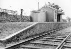
Rob's photograph taken at Mendlesham seems to be perfect for me:
  1. The Middy arrived about fifteen years after my fictional Heybridge railway and so for my back story I am very happy to see the style of the track copied by the new railway.
  2. With the staggered joints, all of the sleepers are the same size and I don’t have to worry about representing the broader sleepers at the ends of panels.
  3. With staggered joints and no panels, my PW train needs to carry only rails and individual track parts as needed for minor repairs.

Phil's photograph at Georgmas Junction is useful too. If the HR was using round sleepers, I can have a think about including some of these too. After all, with the Chelmer and Blackwater Navigation carrying timber from Scandinavia, it would be very possible for my railway to source some replacement sleepers from here.

I want to go for 40ft as the length of the rails to be represented. Simply because this will be much easier for the railway to handle, and to include as a scenic detail if wanted.

I have enough prototype information to make a start, and I can return to modelling techniques here.

Thanks ever so much for all of the prototype notes.
 
Top