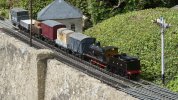
The Heybridge Railway, 1889 to 1913

Richard Gawler

Western Thunderer
The baseboard kits include MDF spacers 3 mm thick and plywood dowels 6 mm thick. These are all 25 mm diameter. The spacers provide a backing behind dowels between baseboards; the dowels can be the plywood ones or pattern makers dowels. You get plenty of plywood dowels but only the exact number of 3 mm spacers, and the traverser arrived without any spacers at all. So I have made some spacers from surplus plywood dowels.

DSC_3283.jpeg
I glued the dowels onto woodworker's dowels, with the glue only at the outer ends i.e. further away from the chuck.

DSC_3285.jpeg
I removed 3 mm of thickness. The new spacer releases itself when the cutting tool gets near to the dowel in the middle.

DSC_3287.jpeg
I did five of these because the fourth spacer self-destructed near the end of the cut, perhaps there was a void in the plywood. The four new spacers match the supplied MDF ones and are ready for use.

The sawdust rather mops up the lubricant on the bed, I must re-do this soon.
 
Last edited:

Richard Gawler

Western Thunderer
The extra dowels arrived yesterday and I have finished building the baseboards.

The fun stopped for a while because the all of the alignment holes in the ends of the traverser module turned out to be set lower than those on the all of the other baseboards. The effect would be to raise the whole traverser module. I asked the manufacturer about this and it turns out my bargain second hand traverser (bought from a third party) is a special made for someone who wanted a higher deck to compensate for underlay elsewhere :rolleyes:

Well, it wouldn't be much of a hobby if it everything was easy. Most every idea to sort things out would turn the layout from being a modular one into a sectional one, so I ended up moving the holes . . .

DSC_3299.jpeg
The traverser arrived with the 25 mm dowels fitted flush into the frame. These came out with a Forstner bit, some more cleanly than others.

DSC_3293.jpeg
Then I opened up these holes using a sort of side-and end-cutting milling cutter in the Minicraft drill, added the 3 mm spacers and plugged all of the too-low 6 mm holes.

DSC_3307.jpeg
The pattern makers dowels and their sockets are fitted with rather a lot of epoxy glue and their usual screws.

For the two sockets, I put cling film over the two dowels on module (A), this kept the surplus glue at bay and let me separate the joint afterwards

DSC_3304.jpeg
This is the completed fiddle yard in its "maximum" configuration.

DSC_3301.jpeg
Every instruction followed.

DSC_3303.jpeg
So I now have my four baseboard modules. Every module connects to every other module, with the exception that nothing connects to the far end of the diorama because I have no need to do this.

I need to build some kind of sub-frame to hold the modules, this needs to adaptable enough to hold the modules chosen for the day, be presentable enough for use at home and fit into the back of a Yaris. Another day.
 
Last edited:

Richard Gawler

Western Thunderer
A neat fix and workaround.
Did you really have the board ‘This Way Up’ or did you cheat and invert the photo?

It's the way things worked out and I thought it was a bit of fun. I stood the assembly of boards in the garden with the dowel sockets at the bottom and the dowel pins at the top, and the writing was this way round.

I never manipulate my photos unless it is really obvious (like a ghost image of a motor inside a semi-transparent loco) or to crop or adjust for my less than ideal lighting.

A micro rant follows, which does not add to the usefulness of this post but I might as well get it off my chest now.

Some years ago I saw photos of 00 gauge models stretched horizontally (to make the track look better) and the smokebox doors were oval. If it was a ploy to sell magazines, it backfired for me.


Edit: so that's what the "spoiler" feature does! I wonder if it can do something more useful?
 
Last edited by a moderator:

Richard Gawler

Western Thunderer
View attachment 188113
Here are three of the four modules resting on the board of my old test track. The track bed is now a little too high for comfort, but not much.

The main thing here is to show how the traverser can hold three tracks plus space for loose stock at the back. This arrangement means I use only part of the movement available, the deck doesn't collide with the display cabinet and I can always (just) reach the far corner of the layout.

I do think, the modules should be single-sided. That is to say, any module connects to any other but always with their outer sides facing the same way. Trying to get three tracks to align over four baseboards in every permutation is a bit too ambitious for me, so having the boards facing the same way greatly reduces the scope for errors. This also means, the dowels will be two males on the left and two females on the right for every module.

The Ikea Kallax on its steel frame (also Ikea) would make a really good base for the layout if it was a little higher. Perhaps find some longer screw-in feet or even some castors.

Ten days on, here is a fresh view of the baseboards to wrap this part of the project up for a while.
DSC_3332.jpeg
The board from my test track is now the foundation for the new boards. The Kallax underframe is on castors and the baseboard tops have ended up about 1.15 m above the floor. I find this comfortable for using three-links but too high for scenic work. The castors mean there is now room to store the fourth module under the Kallax underframe.

I have put the wagons here to get a feel for what this scheme can hold. There are four internal, two PO and two foreign. This is about the maximum without getting completely boxed in. The 200 mm headshunt module (in the distance) can hold Nellie and Blackwater (and my next two loco projects) but not Nellie with her tender truck nor (of course) the Y14.

I suspect the diorama would work better as a "small layout" if the loco spur came from the fiddle yard not the kick-back siding; but will be a better "test track" with the kick-back using the Setrack point. Maybe there is a compromise somewhere in here but my gut feeling is, this is my scenic test piece and test track; and The Layout is for later.
 
Last edited:
Gloucester 4-plank wagon (1870s)

Richard Gawler

Western Thunderer
Of course!

View attachment 187671
Coming next - a ballast wagon from Gloucester.

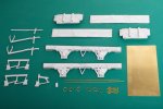
Three weeks later than intended, I am building a dumb-buffered wagon from a white metal kit by Jim McGeown, the proprietor of Connoisseur Models. This is an old kit from some years ago, which Jim has asked me to have a go at building. I have a feeling the kit might reappear in Jim’s catalogue if people ask him for it.

DSC_3195.jpeg
1/ The kit includes the parts to let you build the wagon with an early-style brake acting on one wheel, or a more modern brake acting on two wheels on the same side. I am building the earlier version so the model can look suitably at home as a ballast wagon on my late Victorian railway.

First impressions are extremely good; this kit (like others from Jim) seems to have been designed to let the purchaser actually build a model without having to re-work or renew key parts. For someone whose first attempt at a white metal kit was a Will’s GWR U1 tank (4mm) around 1980 and hasn’t done many such kits since, the castings are a revelation.

This is my first attempt at assembling a white metal “railway” kit (as opposed to a static “scenic” kit) using solder. All of my previous attempts at loco bodies and wagons have used epoxy glue, so please bear with me if there is more detail here than we really need.

DSC_3339.jpeg
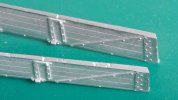
2/ There were some pinholes in the tops of the long sides, which I filled with 100-degree solder. I am doing the whole build with this solder unless I say otherwise.

DSC_3343.jpeg
3/ The flash around the W irons (photo 1) was really thin and came away with a knife and by prodding with a cocktail stick. After I cut off the supports for the modern brake gear, I found small holes in the solebars and these holes proceeded to open up when I tried to fill them with solder. Discretion took over here and I filled them later with Milliput.

DSC_3350.jpeg
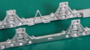
4/ I tacked the sides onto the solebars and then soldered the joints solid. Then I put in the first three wheel bearings . . . the holes in the axleboxes need to be opened up but the castings come with a rebate (photo 3) to hold the flanges of the bearings.

DSC_3352.jpeg
5/ I have drilled out one of the axleboxes oversize (3 mm instead of 2.5 mm), the idea is to use this bearing to set the two axles parallel with each other.

There are eight cylindrical holes on the insides of each solebar. I guess these reduce stresses during cooling so the castings come out of the mould nice and straight. I filled all of these holes with Milliput. Any filler which uses water as a lubricant and can set underwater too has got to be good, although sadly this one doesn’t stick to brass very well. I used Milliput to fill the holes I found at step 3 as well.

DSC_3358.jpeg
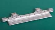
6/ I am assembling the model around its brass floor panel and I have soldered the first side to the bottom of the floor as well as to the top.

I put these efforts into the ultrasonic bath to complete the day. I dipped my fingers into the water too and discovered the machine cleans out the dirt under finger nails pretty well. I have also just realised none of the photos show the outsides of the wagon but they are looking good and will appear in the next installment :)
 
Last edited:

Richard Gawler

Western Thunderer
DSC_3376.jpeg
7/ I am building the Gloucester wagon kit around its brass floor panel. I placed the wheels and their fourth bearing loosely into position and then tacked the second solebar into place underneath the floor. With this solebar truly opposite the first one, a tiny bit of endplay on the fixed axle, and the long side nicely perpendicular to the floor, I soldered the side solid onto the top of the floor.

I play things a bit fast and loose with this sort of soldering, i.e. run the iron a bit hotter than it probably should be. This gets lots of heat into the brass and the casting, the solder flows well, and the casting has enough mass to take the excess heat away without starting to melt. I am steadying the model with my fingers, so when the casting gets too hot to hold I stop for a while. The solder melts at 100 degrees C, and the bit is hot enough to melt 145 easily but probably not 188. This way I find there is hardly any cleaning up to do afterwards.

DSC_3363.jpeg
8/ This is my method of persuading the wagon to sit flat on track. The fourth bearing (front left) is pressed home with a cocktail stick to set the end float and then set in epoxy glue dropped in from the front of the axle box. The model stays on its side for ten minutes so the glue sets enough to stay put and is then hung upside down from its axles on a flat bit of metal. For me this is my try square resting on a suitably ramshackle support. After the glue has set enough to be "movable with difficulty", I use internal calipers to make sure the second axle is parallel to the first in the horizontal plane.

This is where I relax; the threshold where the build changes from the essentials to make a working model to casually adding the details. This model actually runs extremely well, probably because it is twice the weight of my brass and plastic ones.

DSC_3381.jpeg
9/ The ends have to drop into place from above and so the large flange (intended to sit below the floor) gets in the way. I cut a broad groove (12 inch hacksaw) to make sure the ends don’t foul the ends of the floor, and then cut off the flange.

DSC_3390.jpeg
10/ The ends fit well and the mitred corners fit perfectly on the inside, but there are joints to fill on the outside.

DSC_3392.jpeg
11/ I used 70 degree solder for the outside corners, mainly because I want to use it up and keep the 100 degree solder for other tasks. The kit instructions are particularly good at explaining how to do this.

DSC_3405.jpeg
12/ I struggled with one corner and after messing it up twice I tried to make the angle iron look like it has been hit by a crane. Quite whether this looks like "realism" or "shoddy modelling" will show up better after painting.

DSC_3412.jpeg
13/ The kit includes a brass etch for two coupling hooks. The hooks are only a single thickness, I doubled them up to make a better-looking hook for one end. The hook for the other end can follow later. The horse hooks (one each side) are from the brass wire supplied in the kit.

This completes the build using parts in the kit except for the brake gear and the coupling links, which I want to add later.

Everything here is from the kit, except for the wheels (Slater’s 7120) and their bearings. To give a short mid-build conclusion, the provision of a brass floor makes construction as straightforward as humanly possible. I have encountered (but not built) white metal wagon kits supplied with a styrene sheet floor, and if I ever wanted to build one of these I would begin by buying some brass sheet and cutting out a new floor.

DSC_3402.jpeg
I think the wagon is going to look at home with my other kit built models, including older kits like the Three Aitch van and more modern ones like the Slater's open. I want to add some details of my own, but I need to have a think about what these will be.
 
Last edited:
Richard Gawler

Western Thunderer
Here are a few more photos to show how I am developing the model before the details get hidden under the paint.

DSC_3415.jpeg
14/ This is simply to show how I used the two hooks from the kit to make one thicker hook.

DSC_3424.jpeg
15/ I have added some strips of brass along the tops of the sides and ends to represent the steel bars attached here to protect the top planks from knocks. I have tinned these strips to represent bare steel, thanks to @Rob Pulham who has done this on his loco side rods.

The kit instructions suggest scribing the brass floor to represent planks. I am doubtful of my ability to get these uniform and parallel so I have glued in a rectangle of embossed styrene instead. I am pleased with the lighting here and it wll be tricky to do it again so the strand of Evo-Stik stays.

DSC_3419.jpeg
16/ Removal of the cast brackets for the modern-style brake gear has revealed various gaps between the solebars and the floor. Sorry about the colour cast on the wheels but attempts at different lighting just made everything green :D

DSC_3418.jpeg
17/ I have a rectangle of laser-cut plywood to represent the floor planks underneath. This can go on after most of the painting, it will hide the gaps at the tops of the solebars and provide some packing to help set the single-wheel brake at the right height. The hook on the right is a cast brass one of unknown provenance. I’m not sure how I end up with quite so many single hooks in the spares box.

This takes the model as far as I can go before painting.
 
Last edited:

Richard Gawler

Western Thunderer
I made a serious error of judgement in leaving the brake gear off the wagon until after painting. Fixing the three parts of the brake into place with glue has proved difficult and time consuming, so I know for next time to build a whole wagon and then work the brush around the small details as needed.

DSC_3444.jpeg
I found the casting for the single brake needs to be fixed about 2 mm below the brass floor to obtain a good fit between the brake block and the wheel. I found these two millimetres using the ply floor panel and a strip of 1 x 1 mm brass rod. The blobs on the solebar are epoxy glue I didn't see until I looked at this photo.

DSC_3446.jpeg
The area available to fix the brake lever casting onto the solebar proved to be too small to make a robust joint using glue so I ended up inserting a pin from thin brass wire, this secured with CA glue and then hidden under a blob of paint.

DSC_3450.jpeg
The brake block has ended up looking pretty neat.

DSC_3453.jpeg
I find painting models difficult and I feel the results here do not reflect the amount of effort and time I put into trying. Though the results are better than what I managed a few years ago.

For the record, this is Halford's grey primer, Halfords "Ford Polar Grey" (gloss), Tamiya "Dark Iron" and "Flat Earth" for the running gear, and some Vallejo and Ammo Mig acrylics for the inside. I had three goes at painting the "bare wood" on the inside and none of them look much like wood. A load of ballast should help.

The coupling links are temporary fitments so I can run the model in a train. One day I will find some steel chain with links the right size and shape, and use this to re-fit many of my wagons.

The bottom line for this build has got to be, forget adding the brake gear after painting, and see this kit as a straightforward way to build a model of a period wagon with some character. I wonder if Jim (Connoisseur Models Home Page) will put it into production and add it to his catalogue?
 
Last edited:

spikey faz

Western Thunderer
Hi Richard

I built a similar wagon a few years ago. From memory I sprayed the whole lot in Halfords white primer. I then painted the wood parts using a mixture of brown/black/silver to try to replicate faded/worn wood. I thinned the paints (Humbrol) quite a bit to get the paint to flow onto the nooks and crannies. Important to look at a real bit of wood which is often more silver/grey than plain brown.

I may even have washed a bit of green in places to give that sort of neglected look. Weathering powders also worked quite well.

Mike
 

Richard Gawler

Western Thunderer
I like the idea of putting silver into the mix to represent bare wood, I want to have a go at this.

In the meantime I have discovered I can remove the overspray of brown Tamiya using Vallejo brush cleaner on a cotton bud.

DSC_3455.jpeg
Well, shuffle the brown around if not completely remove it. I am a lot happier with this.

The Ford Polar Grey (Halfords) has a high gloss and this doesn't do a cast model any favours, only the bounced flash is hiding the gloss here. I want to leave the outside alone for a while and then give it a dusting of a matt enamel varnish.
 
Last edited:
Wagons for the railway - internal, private owner and foreign

Richard Gawler

Western Thunderer
DSC_3466.jpeg
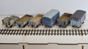
The Heybridge and Langford Light Railway now has all of its own wagons:
  • the tender truck serves as a combined loco coal wagon and shunter's truck (it looks best coupled to Nellie the crane tank)
  • next are two opens, one for PW equipment and other internal operations and one for ballast
  • there is a van and an RCH open (Dapol), both for commercial traffic within the limits of the railway
  • the ex-Mid Wales Railway break van would have been replaced by something more modern around 1906
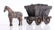
There is also the chaldron wagon (more loco coal), which I see as a scenic feature, perhaps with a horse.

I think a nice thing about this collection is that I have kits from white metal, brass, plastic and MDF, and only one RTR; and there isn't likely to be another railway out there quite the same as this one.

One day I can have a go at repainting the various "bare wood" interiors.
 
Last edited:
Richard Gawler

Western Thunderer
Le Mans start :cool:
The only reply I can think of is to post some photos of the two "secondary races" :)

DSC_3480.jpeg
The railway can enjoy three PO wagons so far. Most of the coal here arrived by coastal shipping from the North East (to Heybridge Basin), but I imagine E H Bentall bought in wagonloads of high grade Welsh coal for their iron smelting operation. The tar is for the building trade, my chosen 1889 to 1913 setting is too early for sealed roads. I am getting better results repainting the bare wood interiors of my RTR wagons than painting the insides of my kits.

DSC_3489.jpeg
Wagon design and technology changed a great deal from 1889 to 1913 so my selection of foreign wagons gives the opportunity to keep on making fresh models. The only limitation is being able to dream up suitable loads for them to bring onto the railway, but timber from Scotland and engineering products from Bristol (earlier and later wagons) are reasonable. I am also supposing, local workers came here from Scotland, and grandparents sent a wagon load of clothes and presents from time to time.

The main gaps are some PO wagons belonging to E H Bentall and the (fictional) Heybridge Salt Company, and something belonging to the GER. I have some RTR models and kits to tackle these, but while they are "important" I can see other models I want to build first. I also have some other foreign wagons built and painted (and posted here during the last year or so) but needing transfers.
 
Last edited:
Charlie - painted

Richard Gawler

Western Thunderer
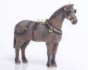
After all of the problems I had with the stationary boiler from Duncan Models I have assembled a horse from the same source.

View attachment 185963
This is two whitemetal castings plus detail parts, and the parts fitted together with only a little filler. There was hardly any cleaning up to do either, much better.

Painting is another matter for me, this is going to get subcontracted out.
'Charlie' returned from Dan Evason (Tunnel Lane) yesterday and, well, I think his work here is fabulous.

DSC_3500.jpeg
My brief was, "he could be a brown or a grey, whichever you like". Definitely worth sharing, I wouldn't post my own painting efforts at this level of enlargement.

DSC_3491.jpeg
I intended Charlie to pair up with a Phaeton, but I think he looks good with the chaldron wagon. The setting (when I build it) is, after all, primarily a model railway layout.

Charlie wears a harness for a light horse. From looking at old drawings, I believe this is fine for moving the chaldron or a small cart. Charlie had a namesake who was the last working horse on BR, a larger horse with a heavier harness tasked with moving much bigger and heavier rolling stock.
 

Herb Garden

Western Thunderer
'Charlie' returned from Dan Evason (Tunnel Lane) yesterday and, well, I think his work here is fabulous.

View attachment 189607
My brief was, "he could be a brown or a grey, whichever you like". Definitely worth sharing, I wouldn't post my own painting efforts at this level of enlargement.

View attachment 189606
I intended Charlie to pair up with a Phaeton, but I think he looks good with the chaldron wagon. The setting (when I build it) is, after all, primarily a model railway layout.

Charlie wears a harness for a light horse. From looking at old drawings, I believe this is fine for moving the chaldron or a small cart. Charlie had a namesake who was the last working horse on BR, a larger horse with a heavier harness tasked with moving much bigger and heavier rolling stock.
According to the GER journal the standard 1hp yard shunting Locomotives from 1839 to 1923 were of classes GG1 and GG2 the difference being variation in below solebar details. I am unsure of the classification the LNER used for these versatile machines.
 

Richard Gawler

Western Thunderer
I am unsure of the classification the LNER used for these versatile machines.
On the basis of my Y14 (ex-J15) project, then numerically GG1 and GG2 became the RG2 and RG3 under the LNER. This makes sense, because I am RG.

Edit: Maybe I can find room for another one on the layout. They were such an important part of the railways.
 
Last edited:
Richard Gawler

Western Thunderer
I do admire the people who can create a sculpture like a 7 mm scale horse and make it look so realistic. There is so much detail here in the muscles and rib cage which show so much understanding of way the animal is made. And the pose looks so contented too, just right for a "standing and waiting" role on the layout.
 
( Diversion : GER Y14 returns to Ambergate as a complete loco )

Richard Gawler

Western Thunderer
Trial runs on a stud-contact garden railway

View attachment 175492
A trial run of the Y14 chassis plus tender on the railway belonging to a club member was very promising, with the chassis hauling its "power pack" plus their 16-wagon train with ease and needing only the 4 oz weight to provide enough adhesion. So it looks like the body (not started yet, probably 250 grams) will give the chassis enough adhesion to haul a decent train without adding much if any additional weight.

View attachment 175491
Some of the trackwork dates back to the 1960s. The owner build the pointwork without plans or standards, and the crossing flangeways are a little more generous than Peco Setrack ones. So the Slater's FS wheels gave a pronounced wheel drop, but they stayed on the track.

View attachment 175490
The only problem was derailments caused by holly seeds, of which there were a few dozen to pick up.

The garden is large by modern standards . . . I carried the r/c transmitter about 18 m (say 60 feet) away from the loco and control remained robust. This distance is further than I can imagine wanting to go to control a model train.

So really, a fine trip out.

A visit to the Midland Railway.

View attachment 181716

I took the loco to a friend’s railway earlier today. We began with this 16-wagon coal train.

View attachment 181717
The track here is coarse standard and electrified using stud contacts. The loco ran really well everywhere it could cope with the track. It floundered on some of the pointwork with tighter curves (5 feet and less), and where the toll of winter has left a couple of broken fishplates.

View attachment 181718
Then we tried a 30-wagon train. The loco could get this underway and keep it moving on the main line, but ran out of traction adhesion trying to pull the train through a facing crossover. This seemed like being right on the threshold of exceeding expectations. I added 110 grams of weight to the loco and it did exceed them. (The train is on the 'wrong line' here because it is too long for the train turntable behind it, and it will shortly cross to the correct running line.)

View attachment 181719
This is a freight loco so I will have to imagine this is a working of some empty coaching stock during some kind of trial or locomotive exchange with the Midland.

Only four photos but all in all this was a wonderful time. The loco works, and works well. The major unknown now is how long it can run on a charge of its batteries. I suspect this will vary so much according to speeds and loadings I will never really know.

I left my Y14 untouched for a full month. I was convinced I could hear something binding in the chassis (my ply baseboards do rather amplify this sort of thing) but a mate said the running seemed perfect to him.

Received wisdom was to give the loco a run before trying to improve anything, and the opportunity to do this arrived yesterday.

P1050232.jpeg
So, back to the Midland Railway at 'Ambergate'.

P1050244.jpeg
This double junction has its origins in the 1960s. The builder did not know the standards for trackwork at the time, and so they devised their own. I suppose, the work is a little tighter than today's GOG 'coarse standard'.

P1050236.jpeg
All of the running was tender-first because the tender weighs as much as three wagons and I thought this was a suitably demanding scenario.

P1050237.jpeg
The model performed faultlessly and never derailed during I suppose a total of ten out-and-back round trips.

P1050242.jpeg
The regional discrepancies seemed to be accepted by all.

The loco really does need a crew. I have painted two sets but they are dressed for the 1950s and I want something for the late 1890s - I still need to find out what this is. Although anything would have looked better here.

This was a NEEGOG club meeting and really was a grand day out. Several people commented on how well the loco ran so I must reassess my own standards of what is adequate. The loco ran at least 300 metres in all and never derailed so it might be best to leave the chassis alone and continue the running-in another day. I wonder how long this should take?
 
Last edited:
Top