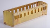
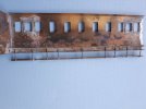
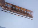
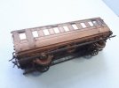
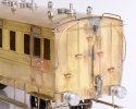
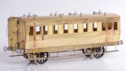
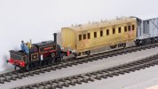
The Heybridge Railway, 1889 to 1913

Richard Gawler

Western Thunderer
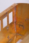
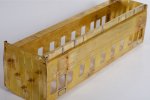
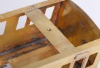
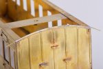
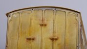
Looks like a loco boiler now, well done.

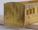
Thanks Phil. I think it will be wise to stop now. If I can paint the model and then add some wooden bungs and boards, I think the model will give the right impression.

Simon yes some more holes would be good, perhaps a smaller diameter, but I would want the tube plate flat on the bench to mark it out for drilling. I don't have much chance of getting them in straight lines on the assembled model, and no detail is better than bodged detail.

DSC_2427.jpeg
The infuriating thing is, when I was browsing through the parts I was going to fit the tube plate the right way up. Then I looked at the instructions and the photo on the front of the box and just blindly followed them. Even the manufacturer of the kit has put the tube plate on upside down :headbang:
 
Four-wheel saloon - body, solebars, floor and roof

Richard Gawler

Western Thunderer
My next project is a 4-wheel saloon coach from a kit by Connoisseur Models. This is my first attempt at building a coach kit. I have tried to modify RTR coaches e.g. cut and shut and even new sides on RTR in smaller scales, none with much with success so hopefully a purpose-made kit will work out better.

I am not sure whether my Heybridge Railway actually needs this coach. It might be there to supplement the brake coach for fair days and market days. I want to build the brake coach with fairly heavy modifications of the source kit so some practice will be good. If I don't want the saloon, or the layout just cannot be big enough to hold a two-coach train then I can treat it as a learning kit to sell on after completion.
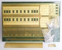
DSC_2446.jpeg
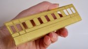
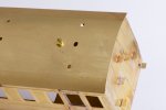
The kit comes with a prerolled roof, good because I don't have any rolling bars and the roof is going to be conspicuous on the finished model.
I bought the kit at Kettering on 5th March, it is secondhand but unbuilt so a modest cost saving over buying a new one.

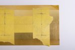
Work begins by forming the sides, beginners luck maybe but this these turned out pretty well.
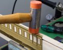
DSC_2481.jpeg
I don't have any folding bars either so I formed the tops of the sides in the vice. There is a half-etched bend line and I scored this very heavily using a scriber, and then worked the flange over I suppose about 15 degrees at a time. This is not ideal because it tends to stretch the narrow strip of flange. Afterwards I worked the flange down onto a piece of plywood from an old drawer unit (nice square edge) and the ripples have pretty much vanished.
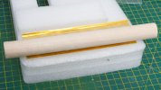
DSC_2447.jpeg
The newest additions to my armoury are an offcut of hardwood dowel and a piece of dense foam. This is the sort of shiny rigid foam which comes in blocks formed by layers bonded together. Anyway, I formed the turnunder by pressing the dowel into the side. I didn't roll the dowel very much. I doubt this approach would work on a mainline coach but on this one the results just came out perfect first time.
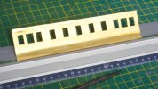
DSC_2453.jpeg
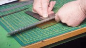
Working the fold for the flange at the bottom was more difficult than the turnunder but easier than the flange at the top. I am holding the flange flat onto the bench with the straight edge whilst lifting the side with the steel rule.
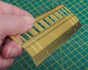
DSC_2448.jpeg
Part way round.

DSC_2460.jpeg
Bonus picture because I had a visitor and they held the camera. I am shoving the flange into place with the back of the square.
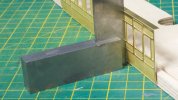
DSC_2484.jpeg
Result :)

DSC_2462.jpeg
Hopefully this photo shows the shape created using the bit of dowel is actually pretty good.

Small thought:

When I was writing technical publications for a living we decided to exclude tools and body parts in photographs. The only exception being the use of a tool in an unconventional way e.g. using a using a screwdriver to prise off a blanking cap. Having a distant and impersonal look is fair enough for system build and maintenance manuals (and the only practical way if you want a consistent hand in the photos) but maybe it brings a bit of life to a workbench topic?
 
Last edited:

Daddyman

Western Thunderer
I've built the kit in 4mm and it's very nice. I have another to do in 4mm and one in 7mm! The 4mm kit is shot down from the 7mm, so the latter will have the same foible: I found that the supports for the lower stepboards were in the wrong place - behind rather than in front of the solebars (there are just dummy brackets to go on the solebar fronts). That may work in 7mm - I don't know - but in 4mm it both looked wrong and the supports fouled the axlebox castings. In the end I folded wire supports into a U-shape channel, with one arm of the "U" going under the upper step as the attachment, and one under the lower. A jig can be used to bend all the "U"s consistently; the distance between the underneath of the upper board and the top of the lower seems - from Alan Wright's North Sunderland book - to be 1'3". It may be that none of this is necessary in 7mm, with materials being proportionally thinner.
 

Dog Star

Western Thunderer
What a clear and informative photo-essay in how to form a brass etch coach side, an enjoyable read.

Pleased to see the correct term for the way in which the coach panels are shaped to meet the bottom side, turnunder is just the ticket.

regards, Graham
 

King Crab

Western Thunderer
My next project is a 4-wheel saloon coach from a kit by Connoisseur Models. This is my first attempt at building a coach kit. I have tried to modify RTR coaches e.g. cut and shut and even new sides on RTR in smaller scales, none with much with success so hopefully a purpose-made kit will work out better.

I am not sure whether my Heybridge Railway actually needs this coach. It might be there to supplement the brake coach for fair days and market days. I want to build the brake coach with fairly heavy modifications of the source kit so some practice will be good. If I don't want the saloon, or the layout just cannot be big enough to hold a two-coach train then I can treat it as a learning kit to sell on after completion.

View attachment 183677
The kit comes with a prerolled roof, good because I don't have any rolling bars and the roof is going to be conspicuous on the finished model.
I bought the kit at Kettering on 5th March, it is secondhand but unbuilt so a modest cost saving over buying a new one.

Work begins by forming the sides, beginners luck maybe but this these turned out pretty well.

View attachment 183684
I don't have any folding bars either so I formed the tops of the sides in the vice. There is a half-etched bend line and I scored this very heavily using a scriber, and then worked the flange over I suppose about 15 degrees at a time. This is not ideal because it tends to stretch the narrow strip of flange. Afterwards I worked the flange down onto a piece of plywood from an old drawer unit (nice square edge) and the ripples have pretty much vanished.

View attachment 183678
The newest additions to my armoury are an offcut of hardwood dowel and a piece of dense foam. This is the sort of shiny rigid foam which comes in blocks formed by layers bonded together. Anyway, I formed the turnunder by pressing the dowel into the side. I didn't roll the dowel very much. I doubt this approach would work on a mainline coach but on this one the results just came out perfect first time.

View attachment 183680
Working the fold for the flange at the bottom was more difficult than the turnunder but easier than the flange at the top. I am holding the flange flat onto the bench with the straight edge whilst lifting the side with the steel rule.

View attachment 183679
Part way round.

View attachment 183682
Bonus picture because I had a visitor and they held the camera. I am shoving the flange into place with the back of the square.

View attachment 183685
Result :)

View attachment 183683
Hopefully this photo shows the shape created using the bit of dowel is actually pretty good.

Small thought:

When I was writing technical publications for a living we decided to exclude tools and body parts in photographs. The only exception being the use of a tool in an unconventional way e.g. using a using a screwdriver to prise off a blanking cap. Having a distant and impersonal look is fair enough for system build and maintenance manuals (and the only practical way if you want a consistent hand in the photos) but maybe it brings a bit of life to a workbench topic?

I personally like to see a hand, or finger, in the shot.
It helps to get an idea of the scale of the object.
Otherwise it can be hard to work out exactly how big the thing being described actually is!

Peter
 

Richard Gawler

Western Thunderer
Thinking about the lower stepboards ( @Daddyman ), I have studied the instructions for adding the footboards but without very much comprehension. I expect everything will become clearer after I have formed up the solebars.

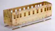
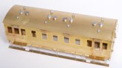
In the meantime I have added the droplights, ventilators and door hinges, and assembled the four sides to make a box. This has all been incredibly easy, like Duplo in brass. The kit gives you a lot of model for your money but not very many parts (yet). I suppose, the next stage of complexity would be to have the panel detail as a separate overlay. This would be fiendish to get square and I am very happy to have the sides and ends half etched. I expect their lack of thickness helped me forming the turnunder with dowel and foam a great deal, a full-thickness side would be more difficult.

DSC_2514.jpeg I am making a special effort to do neater soldering. I am using solder paint for the details and some 60/40 multicore for the corners, all with the microflame torch not the iron. The 60/40 seems to work just as well as Carr's 188, I am ingoring the rosin cores and using 9% phosphoric acid as the flux.

DSC_2507.jpeg
The sides and ends are very thin (because of the half etching) and the heat of the flame is bringing a copper colour to the surface. This effect wipes off with wire wool, I don't think it is doing any great harm.

DSC_2523.jpeg
Opposite corner. The assembly of the sides has needed hardly any cleaning up, the parts simply fitted together. I measured the diagonals to check for squareness and they are within 0.5 mm of each other.

The instructions tell you to dress the external corners to make them sharp. I know, DIY paint won't stick to a sharp edge and I guess model paint is the same? Anyway, a truly sharp edge doesn't seem quite right, so I have run a file across them to soften the look. Those door hinges must have been microscopic in the 4mm scale version.

Back in the autumn of 2021, when I was still starting out in 7mm scale, I thought how much I would like one or two of the Dapol Stroudley coaches. So I registered with Hattons to tell me when they came into stock. Fast forward 18 months to March 2023 and I bought this kit. Four days later, the stock notification arrived from Hattons. Too late :D
 
Last edited:
Daddyman

Western Thunderer
The instructions aren't very clear, are they? This is what they want you to do (not, I stress, my soldering! - an ebay rescue). As said, those uprights are in the wrong place, from a visual point of view, and in 4mm they foul the axlebox/spring castings.
20230330_102700.jpg
20230330_102713.jpg
This is how I did it in 4mm:
20230330_102525.jpg
 

Daddyman

Western Thunderer
I suppose they were fitted to facilitate cleaning. It's definitely prototypical, as photos in Alan Wright's book on the North Sunderland and David Dunn's photos of same in Northumberland Branch lines: 1 show
 

Richard Gawler

Western Thunderer
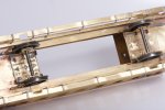
Here is a sample solebar from the 7mm version of the kit.

DSC_2530.jpeg
I ignored the instructions and added the supports for the lower footboard while the part was still flat on the etch. I think this is easier.

DSC_2534.jpeg
Then I formed up the solebar and dropped it into place for this photo.
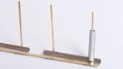
  • The slots on the face of the solebar are for the upper footboard
  • The holes in the underneath are for the hangers for the lower footboard
  • The arrangement at the ends of the solebar looks different to the 4mm model, the lower edge of the headstock is straight and doesn't have the angled part at the ends
I promised myself I would build this model per the instructions and without "improving" it, but I think some 1/4 x 1/8 inch box section would make a better solebar. And, for my own railway, I don't really see the need for the lower footboard. It would be difficult to imagine a cleaner standing on this with nothing to hold onto, and the station platforms will be high enough to let a passenger step across onto the lower upper footboard.

I can build the model the designer made in the kit, or build the coach I want for my own railway, but at the moment it seems not both. I do want a coach to look at home on my own layout, not a replica of one on the North Sunderland branch.
 
Last edited:
Richard Gawler

Western Thunderer
177301.jpg
I don't have photographs of the NER/Sunderland Railway coaches, but a look at this GER coach suggests to me, the use of wire to hold the lower footboards on the model is a reasonable thing to do.

The provision of a lower footboard, and the style of upper footboards (continuous or only below the doors) seems to vary from one railway company to another. For example (at a glance!) the GWR provided everything and the Southern as little as possible.

Looking at the provision of holes in the kit solebars, and the GER's style of footboards (and even ignoring the price of brass box section!) I think it will be best for me to make the most of the parts provided in the kit.
 

Richard Gawler

Western Thunderer
The instructions aren't very clear, are they? This is what they want you to do (not, I stress, my soldering! - an ebay rescue). As said, those uprights are in the wrong place, from a visual point of view, and in 4mm they foul the axlebox/spring castings.

The instructions are strange: I understand them perfectly now I have assembled the footboards, yet if I try to re-write them I can make something different but not much clearer.

I do know, there is plenty of space for the cast axleboxes and springs, these are not going to foul the footboards.
 

Richard Gawler

Western Thunderer
Footboards.

DSC_2536 (1).jpeg
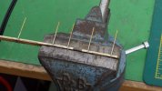
Lower footboards formed to shape in the vice and then their droppers assembled onto both footboards together. Fresh pieces of ply with scorch marks.

DSC_2540 (1).jpeg
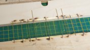
Droppers cut to separate the two footboards and then formed into uprights in the vice. These are the tightest bends I can manage.

DSC_2554 (1).jpeg
Offcut of tube makes a cutting guide for the droppers.

DSC_2558 (1).jpeg
The droppers then go tight against the insides of the solebars.

DSC_2555 (1).jpeg
I have shortened the upper footboards so they are only present below the doors. This leaves the brackets on the fronts of the solebars a bit short. Too short for a perfectionist (and this could be me) but somehow I don't think they will shout out on the finished model. Unused slots in solebars filled with brass wire soldered in from behind and then filed flat on the front.

Everything about this kit seems to have been thought through very well. The only rework I have done has been to nudge some of the droppers downwards by 0.5 mm or so to make sure the lower footboards are truly straight. Next time I might put shims behind some of the ventilator etches so they appear to be open, as on the 4mm scale example posted a few days ago.
 

Richard Gawler

Western Thunderer
Structural floor panels.

DSC_2559.jpeg
I am now deviating away from the instructions, I can't help it :oops:

The kit provides a roof (of course) but no floor, and think the roof will tend to pull the body crooked. Also the body seems vulnerable if the model should take a tumble onto the floor. The instructions warn against using a brass floor because this will amplify noise from the wheels and track.

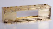
The two panels above are what I could do using sheet brass to hand. They are holding the body square at solebar level and they have reduced but not removed the propensity of the body to twist. Putting these panels inside the body means they will let a cosmetic wooden floor sit above the lugs protruding upwards from the solebars. There is space to put a sheet of 2 mm foam underneath if sound deadening is wanted. In the meantime the model stays entirely metal and I can keep on washing it.

My thoughts now go to making the roof detachable (I have guidance from Ken @chigley) and providing a rocking arrangement for one of the axles.
 

Richard Gawler

Western Thunderer
Attaching the roof.

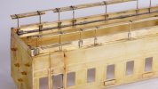
I want the roof to be detachable so I can work up the interior of the coach. My method is to put two 6 BA screws downwards through holes in the roof and into brackets placed across the width of the body.

DSC_2562.jpeg
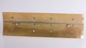
All holes marked out with pencil on masking tape. The tape helps to keep the centre punch where I want it to be and stops it sliding.

DSC_2568.jpeg
I made two of these bracket to hold the roof, one at each end. This idea is from Ken (@chigley ). I put a 6 BA nut underneath to accept the screw through the roof. Adding these brackets has made the whole body a great deal stiffer and more resistant to twisting. I expect the interior floor will now have to be in two sections to let it go in.

DSC_2564.jpeg
0.45 mm wire making a correction to the roof profile. I did this at both ends. Perhaps I should have fixed the ends 0.5 mm higher; this would have needed minor adjustments to the bottom corners of the sides.

DSC_2587.jpeg
The two screws are clamping the roof flatter than its rolled shape but I have still ended up with this gap at one corner. The other end is better. The funny thing is, a photo in the instructions shows exactly the same gap. To be honest, I don't think this will show after the model is painted, even with a low camera shot.

DSC_2590.jpeg
I want to use some screws with countersunk heads in place of the cheese head ones. Then I can use two of the lamp covers to hide them.

The masking tape did do its job here for the lamp hole, but I put the centre punch in the wrong place. It won't show afterwards :D
 

Richard Gawler

Western Thunderer
Roof assembly.

DSC_2592.jpeg
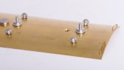
I have added a length of FB rail underneath to reinforce the roof and help it to stay straight when I tighten the fixing screws. I intended to put two lengths of rail but one has turned out to be ample. Somehow this looks a bit ugly. The two nuts are opened up to 6 BA clear and are here to provide some metal to countersink the screw heads on the other side.

DSC_2594.jpeg
I skimmed each of the lamp tops and their covers in the lathe to smarten them up a bit. This is a purely cosmetic excercise but it has sharpened up their various edges. I have now "made" the roof assembly and it is detachable, this was easier than I expected.
 

Richard Gawler

Western Thunderer
Roof fixings.

DSC_2597.jpeg
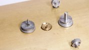
I bored two of the cast lamp hole covers 0.9 mm, trimmed off the cast spigots and soldered in some 0.9 mm wire to make new spigots. Then I drilled two 6BA screws to match.

DSC_2598.jpeg
Two concealed fixings. The modified lamp hole covers are still loose at the moment but I can fix them down when the model is finished.
 
( Diversion : Nellie visits the Middy at Debenham )

Richard Gawler

Western Thunderer
Nellie visits the Middy.

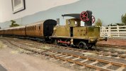
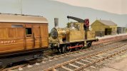
The history of the Heybridge Railway records that Nellie the crane tank was destroyed during the Zepellin raid of the night of 15/16 April 1916. The "might have been" scenario here depicts the arrival of Nellie at Debenham (this was, of course, on the extension of the Middy) and captures the reaction of a passenger waiting at the time.

WhatsApp Image 2023-04-10 at 13.40.28.jpeg

WhatsApp Image 2023-04-10 at 13.44.41.jpeg

WhatsApp Image 2023-04-10 at 13.45.19.jpeg

WhatsApp Image 2023-04-10 at 14.07.59 (1).jpeg

Photos by Tony @Osgood
 
Last edited:
. . part 2 - wheels, brakes and minor details

Richard Gawler

Western Thunderer
Wheels and brakes.

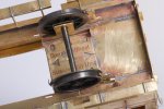
The wheels are running in sprung suspension units, these units are also from Connoisseur Models.

DSC_2615.jpeg
I seem to have stepped in something when I made the two sections of floor. These are offcuts of 2 inch wide brass, trimmed to fit the width of the model. The tops of the suspension units align perfectly, this was not by my design.

There was an option to fix the suspension units with screws and nuts but the fixings would get in the way of a cosmetic floor so I didn't try. It would be easier to hide the nuts in a compartment coach.

DSC_2621.jpeg
The kit has eight brake hangers and I have doubled these up to make the four on the model so they look more substantial. One of them seems to be delaminating. At the moment, the springs are 0.015 inch piano wire. These are stiff enough to hold the coach, minus its roof and castings, at its maximum ride height.

I have done some trial runs by propelling the coach along my test track and running is really good including through my usual Setrack reverse curve. The body doesn't show a tendency to wobble, which I was half expecting having put a spring on each corner.
 
Top