The Heybridge Railway, 1889 to 1913

Richard Gawler

Western Thunderer
One of my favourite decoders is the Lenz Silver V2.0 because it has six user-selectable motor drive characteristics. You change a single CV to go from one characteristic to the next until you find the one best for your model. I will make a guess, Lenz are providing different motor drive frequencies this was suggested by @Giles a while ago. If only a r/c speed controller could do the same.

I did ask Steve Foster (of Fosworks) about an integrated receiver and controller board for my Y14 to save space and he seemed to want to steer me away from such ideas. I felt this was reflecting a limited performance rather than his commercial reasons. Perhaps the decoder manufacturers are put off doing this for performance reasons.

I will also guess the decoder manufacturers want to keep their products tiny so they will sell to modellers in smaller scales. Putting a radio receiver on board is going to make them bigger, a printed aerial has a finite minimum size. I do like the idea of crowdfunding but as an individual I expect I would want only two radio/controllers maximum. I imagine the development work and tooling up needs thousands of sales.
 

Richard Gawler

Western Thunderer
Trial runs on a three-rail garden railway

P1040765.jpg
The second trial away from home has also gone pretty well. Coarse scale plain track is straightforward except where small twigs cause derailments. It seems a dead track system will run well as long as debris e.g. leaves is small enough for the loco to run over or push out of the way.
P1040758.jpg
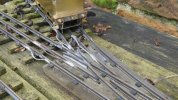
Performance on coarse scale pointwork varies. The loco and tender can negotiate both legs of this point in both directions thanks to relatively tight flangeways beside the checkrails.
P1040755.jpg
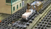
Conversely the loco and tender can manage only the straight leg here. The larger gaps beside check rails and wing rails lead to derailments at every attempt on the curved leg.

Realistically, this means the completed loco should be able to do complete circuits of this railway come the Spring because it will encounter only the straight legs of points on the main line.
 

simond

Western Thunderer
I suspect the combination of the radius/frog angle and checkrail gaps would make those turnouts rather challenging to anything with FS wheels. I doubt your idea of S7 wheels on FS axles would be reliable on the mainline.
 

Richard Gawler

Western Thunderer
I suspect the combination of the radius/frog angle and checkrail gaps would make those turnouts rather challenging to anything with FS wheels. I doubt your idea of S7 wheels on FS axles would be reliable on the mainline.

Yes.

The subject of S7 wheels rather came along with the thoughts on S7 crankpins . . . if I try for S7 wheels they will be on a model intended for static display or for an S7 layout.

The club test track has its faults (it's been around for 30 odd years) and there are gaps in the rails of 2 or 3 mm at some baseboard joins. I am still optimistic for a trial run next weekend; the tender has already proved itself with Nellie. The three-rail system above is by far the most challenging place I expect to share my Y14, and if it runs there next year it will be on the main line with a rake of coarse scale coaches.
 
Last edited:

Richard Gawler

Western Thunderer
Stone the crows! The pre-grouping sleepers I ordered up on 20th September from one of our "small suppliers" arrived in the post today. I can start thinking about my layout plans again.
 

Richard Gawler

Western Thunderer
Trial runs on my 0-MF turnouts

Running through the two turnouts I made to 0-MF standards a while ago is slightly disappointing, I will try to explain why.

DSC_1339.jpg
I have provided about 1.2 mm total side play on the centre axle to let the chassis negotiate a Setrack turnout, which it does.

This axle sits about 1/4 mm higher than the other two (by design) to prevent rocking on uneven track, and so the tyre rarely touches the tops of the rails. This leaves the axle free to slide sideways as its worm gear responds to the forces from the worm. When the loco is running backwards, the axle shifts towards the left side of the chassis, putting the wheel on the right side (photo) closer to the frame. The model runs through the crossing perfectly.

DSC_1338.jpg
When the loco is running forwards, the axle shifts towards the right side of the chassis, putting the same wheel further from the frame. The flange of the wheel hits the nose of the vee.

DSC_1314.jpg
The collision causes the leading wheel to lift off the rails.

These photos show the problem with the wheel on the right and the chassis running forwards and negotiating the left-hand branch of a turnout. Logically a similar problem is going to occur when the loco is running tender first and negotiating the right-hand branch of a turnout.

The model is not going to derail but the behaviour doesn't look very pretty. The only solution I can think of is to add some shim washers to remove most of the side play. This means I have to decide whether the loco should be able to negotiate a Setrack 0-F turnout or a scale 0-MF turnout. I can have either but not both. The decision ought to be a no-brainer, but the sensible choice stops me running the model into the siding on my test track :(
 

Osgood

Western Thunderer
So the problem is caused by the centre axle moving sideways within the motor / gearbox mounting plates as a reaction to forces generated by the worm gear?
If the rear axle were driven there would not be an issue as the centre axle can then float, but this is a big modification.

So, is there any possibility of re-engineering the gearbox to eliminate sideways forces?
If the side frames of the gearbox that also carry the motor were to be mounted on the axle such that they can have no lateral play on the axle, e.g. by collars fastened to the axle each side of the mounting bushes, there would be no side forces transmitted to the axle, and the whole axle and drive assembly would then float through pointwork within the loco frames (albeit with a bit more mass than just a floating axle).
 

Osgood

Western Thunderer
Ah but I see your gearbox sits snugly within the side frames - it will need to have sideplay within the frames equal to the axle sideplay required.

Gearbox.jpeg
 
Last edited:

simond

Western Thunderer
Richard,

it’s not going to do your gears any good either. Ideally you want no free side to side play at all on the axle with respect to the worm, above and beyond what is needed to spin freely. The gears want to stay closely aligned, so they run-in and stay run-in, rather than then wear out!

perhaps put a modicum of free play on the front or rear axle, (or a half-modicum on both…. )

Of course, there is no free lunch, this will increase the maximum crabbing angle that the chassis can adopt.
Probably not an issue unless shunting on curves.
 

Richard Gawler

Western Thunderer
Well, thanks to Tony @Osgood I feel that for the first time in my life I can see a benefit of a floating gearbox - to remove the torque reaction by letting the whole motor/gearbox assembly move sideways.

DSC_1345.jpg
I don't really want to change the gearbox. I can remove the present one by cutting out the motor mount and unsoldering the two sides i.e. destroying it but it has gone in so neatly and with so much solder it really is very solid and it is giving rigidity to the chassis, like an extra frame spacer. The mount is double thickness NS nearly everywhere so quite sturdy.

I thought letting the worm gear move sideways would do it no harm as long as the mesh stayed intact? The spread of grease across the gear stops short of the ends of the teeth here so I would like to think this would be ok - but of course I stand to be corrected.

DSC_1343.jpg
However I have learnt something which surprises me.

I have made this "saddle" from 0.4 mm styrene, it has a slot in each end to let it drop over the axle. This reduces the total free play to about 0.4 mm - about twice what I have provided at the outer axles, and two-thirds of what it was. The result is a chassis which still negotiates a Setrack turnout and curve and now runs through an 0-MF turnout.

I know the styrene has a self-centring effect but I think it is worth trying some shim washers. The worm gear is still going to move sideways a bit but is this really going to cause excess wear?

I've ordered up some 0.1 and 0.3 mm shim washers.
 
Last edited:

Richard Gawler

Western Thunderer
Richard,

it’s not going to do your gears any good either. Ideally you want no free side to side play at all on the axle with respect to the worm, above and beyond what is needed to spin freely. The gears want to stay closely aligned, so they run-in and stay run-in, rather than then wear out!

perhaps put a modicum of free play on the front or rear axle, (or a half-modicum on both…. )

Of course, there is no free lunch, this will increase the maximum crabbing angle that the chassis can adopt.
Probably not an issue unless shunting on curves.

At the end of the day, the only uses I have for my Setrack turnout are on my test plank and on a micro. The Y14 has no place on a micro, and if I add some shims and it runs everywhere except my test plank then I have a reason to make a start on my layout.
 

eldavo

Member
Is the movement of the axle really the problem? Surely if the checkrail in the turnout is correctly placed the axle/wheelset will be correctly guided through the crossing. Sounds to me as though the crossing nose to inside of checkrail dimension is too small.

Cheers
Dave
 

Nigel Cliffe

Western Thunderer
A slightly left-field solution to the gearbox and middle axle would be this:

a) arrange two tubes between the wormwheel and the respective frame bushes, these hold the wormwheel from sliding sideways, keeping it in line with the worm.
b) slot the axle, so a pin can go through the axle from the wormwheel for drive transfer, but allows the axle to slide left-to-right relative to the wormwheel.
c) make a screw with a plain rod on the end to act as the drive screw for the worm to axle.

Cost of trying it is one axle to make the slot, and a few bits and pieces of metal for the remainder. Making the slot is either a lot of careful filing, or access to a milling machine.


For the radio-controlled decoder stuff, there are the new "Blunami" decoders from Soundtraxx appearing. OK they're US sounds, but might offer a possible option on radio ? For European suppliers, such as Zimo, there's a semiconductor crisis to get out of first - they're tens of thousands of microprocessors short (Zimo newsletter) on what has been ordered from suppliers.

- Nigel
 

Richard Gawler

Western Thunderer
Is the movement of the axle really the problem? Surely if the checkrail in the turnout is correctly placed the axle/wheelset will be correctly guided through the crossing. Sounds to me as though the crossing nose to inside of checkrail dimension is too small.

What is happening is, I am building a kit designed for 0 gauge (0-F) and following the instructions to the letter. The result is, fairly unsurprisingly, a chassis which runs on 0-F points (like Peco) but needs to be brought under a little control to work on 0-MF (my hand-built points). The solution is to reduce sideplay but I am stuck waiting for the shim washers to arrive.

If I end up with zero sideplay and the model negotiates a B6 turnout I will be happy. If the model needs a little sideplay to do this, I'll go looking for a friend with a milling machine and some time to spare to put a slot in the axle. Or the real cheapskate solution would be to mesh the worm wheel off-centre with the worm and, when the teeth are worn away too much by the sideplay, move the gear along the axle a bit to use the fresh parts of the teeth (the worm is steel, the worm gear is brass).
 

eldavo

Member
I'm obviously missing something here. Your wheelsets are presumably standard finescale O gauge units. When you say you are building the trackwork to O-MF I assume you are using gauge narrowing to 31.5mm or such like in the crossing and switch area. If this is correct then the only way a wheel can crash into the crossing nose is if the checkrail is too close to the nose of the crossing. The whole reason for the checkrail is to stop wheels hitting the crossing nose and sideplay in the chassis shouldn't change this surely.

What an I missing?

Cheers
Dave
 

Richard Gawler

Western Thunderer
What has happened is two errors have come together in the wrong place. The gauge of the track is dropping to about 31.2 mm opposite the vee, and while the checkrail is in about the right place relative to the stock rail it too is closer to the vee than it ought to be. And, the B2B of the offending wheelset is about 29.4 not 29.2 mm.

Dave, my notes on building the offending turnout are here:
The Heybridge Railway, 1889 to 1913

It seemed alright at the time! . . . I am glad I have found this out with the turnout taped onto a bit of chipboard and the wheels still expected to come off a few more times.
 

Richard Gawler

Western Thunderer
So . . . spot the difference!

DSC_1348.jpg
(A) Failure; the fold-up gauge is clipped onto the tops of the rails and pushing them outwards.

DSC_1355.jpg
(B) Success; the fold-up gauge is resting on top of the rails.

The strips of styrene are about 0.2 mm wider than the slitting disc I used to cut through the timbers, and so the gauge is now about 31.4 mm. The result is, the wheel flange on the driven axle now grazes against the side of the vee but the wheel doesn't climb up the nose. This is without the springy bit of styrene between the wheels. The check rail is doing its job but I need to find another 0.1 mm which I can hopefully obtain by closing up the B2Bs to somewhere nearer their spec.

The main lesson learned here is to let the gauge rest lightly on the rails and not to press it down firmly during assembly. Pressing the gauge down causes it to turn the rails towards the vertical while the chairs are designed to hold them at an inclined angle.

I am a little disappointed with this turnout - the wing rail used by the straight ahead route ended up nearly 1.7 mm away from the vee and there is a discernable wheel drop into the gap. I might try everything again, but using wooden not ABS timbers. I would find the chairs easier to see against a paler background.
 
Top