You are using an out of date browser. It may not display this or other websites correctly.
You should upgrade or use an alternative browser.
You should upgrade or use an alternative browser.
oldravendale
Western Thunderer
What very handsome engines those were!
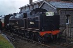
Have to agree!View attachment 182698
If you look carefully at the attached photo, it certainly looks like the cover visible is oval and attached in the vertical plane on this one...
David
OzzyO
Western Thunderer
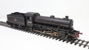
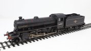
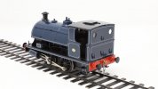
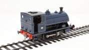
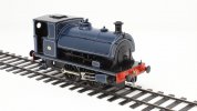
A bit quiet from me recently as work has rather got in the way. However, to brighten my day Paul Moore just sent me these shots of the K1/1 awaiting weathering.
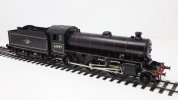
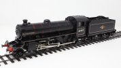
I have put aside the Fowler for a while and am pressing on with a DJH standard 5. Mostly going together OK, but I wish that the instructions included a parts list for each stage.


I have put aside the Fowler for a while and am pressing on with a DJH standard 5. Mostly going together OK, but I wish that the instructions included a parts list for each stage.
One issue about moving the workshop 6000 miles every so often is knowing what to bring. I remembered a selection of BA taps but left behind my metric ones. Guess what is needed for the DJH kit? Anyway, this afternoon I found (with the help of a colleague) a small tool shop close to Taipei main station that was able to provide a full set of three Japanese made M2 taps for just under £9! I may have to see what other sizes they have.
There is a saying in Taipei that whatever you want in the world - and I do mean whatever - can be procured just behind Taipei Main Station.............
There is a saying in Taipei that whatever you want in the world - and I do mean whatever - can be procured just behind Taipei Main Station.............
It's ages since I built a DJH kit. When I was building 00 loco kits I always enjoyed the DJH kits as a cut above the usual run of K's, Wills, Millholme etc. In O I am not so sure. Lots of whitemetal, but fortunately of good quality (so far). Not impressed by the (lack of) instructions. Love the diagrams and photos but at least provide a list of parts to be fitted at each stage. Anyway, 73119 'Elaine' makes progress.

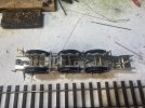
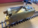
Not much from me for a while - a pesky thing called work. Anyway the tender is now nearly complete. It needs one brake block (missing), buffers (to replace the ones from the kit) and eventually the stretchers fitting.
I suspect I may have made a drop off: I've fitted a water scoop. I know there weren't troughs on the SR but I have been unable to find out whether the standards had them fitted or not. I guess someone is going to tell me that they were not fitted and I have the wrong dome. If so, speak now or forever hold your peace..........
I have revised my opinion of the instructions. I thought they were unimpressive, but having got this far I'll change the assessment to 'dire'. The main reason for this is that I have a piece left over (ET52). I have no idea what it is or exactly where it goes. There is no visibility of it on DJH's photos of the completed tender. Any suggestions? It possibly fits somewhere in the coal space.
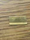
The tender sides come with the lower and upper side radii ready formed. It was only after I had fitted the top to the base that I realised that the radii were not correct. I suggest if you are making one of these you check the form against the tender front before fitting. I also suggest fitting the lamp irons and handrails to the tender rear before forming the tank.
The missing brake block is an inconvenience made worse by the requirement to use DJH's embuggeration form by post (or fax!!!!) to request the part. I would have much preferred to pick up the phone and ask. Or even an email. But post???
The buffer heads are cast with the heads not perpendicular to the stem and with the thread form having no relationship to the M2 form required for the supplied nuts. Fortunately the Gladiator stores have some nice lost wax brass castings with steel heads, so these will be making an appearance.
Apart from these niggles, it has mostly gone together quite well.
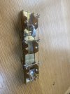
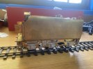
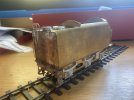
Now back to the loco.
David
I suspect I may have made a drop off: I've fitted a water scoop. I know there weren't troughs on the SR but I have been unable to find out whether the standards had them fitted or not. I guess someone is going to tell me that they were not fitted and I have the wrong dome. If so, speak now or forever hold your peace..........
I have revised my opinion of the instructions. I thought they were unimpressive, but having got this far I'll change the assessment to 'dire'. The main reason for this is that I have a piece left over (ET52). I have no idea what it is or exactly where it goes. There is no visibility of it on DJH's photos of the completed tender. Any suggestions? It possibly fits somewhere in the coal space.

The tender sides come with the lower and upper side radii ready formed. It was only after I had fitted the top to the base that I realised that the radii were not correct. I suggest if you are making one of these you check the form against the tender front before fitting. I also suggest fitting the lamp irons and handrails to the tender rear before forming the tank.
The missing brake block is an inconvenience made worse by the requirement to use DJH's embuggeration form by post (or fax!!!!) to request the part. I would have much preferred to pick up the phone and ask. Or even an email. But post???
The buffer heads are cast with the heads not perpendicular to the stem and with the thread form having no relationship to the M2 form required for the supplied nuts. Fortunately the Gladiator stores have some nice lost wax brass castings with steel heads, so these will be making an appearance.
Apart from these niggles, it has mostly gone together quite well.


Now back to the loco.
David
daifly
Western Thunderer
DavidI suspect I may have made a drop off: I've fitted a water scoop. I know there weren't troughs on the SR but I have been unable to find out whether the standards had them fitted or not. I guess someone is going to tell me that they were not fitted and I have the wrong dome. If so, speak now or forever hold your peace..........
The only reference I can find is that on the Masterpiece website for the 73xxx locos under development:
"They also appeared with a wide variety of BR1 derived tenders: The inset BR1, BR1G and BR1H types as well as the high-sided BR1B, 1C and the BR1F types. Water pick-up gear was fitted on all engines except those on the Southern. Twenty of the Southern engines carried names from scrapped Urie/Maunsell ‘King Arthur’ class locomotives and were known as the ‘Standard Arthurs’".
However, photographic evidence suggests that may only be partially correct. 73000 - 78065 | 73118-Eastleigh-230366-JC889a
This loco (and others that are easily found) show the Standard Arthurs with tender domes. It is impossible to see if the undergubbins - scoop etc. - were fitted or not. This view shows a lot of daylight below! 73000 - 78065 | 73118-Eastleigh-230366-JC889a
This one may help decide: 73000 - 78065 | 73118-Eastleigh-230366-JC889a
Dave
Rob Pulham
Western Thunderer
Hi David,
If you found that fun, just wait until you fit the water scoop gear on an MOK Stanier tender. You have to thread a piece of rod through eight holes, all of which are flopping about their respective pins.
It's a b***er to do the first time, then when you realise that you have fitted the scoop back to front it doesn't get any easier on the next go...
OzzyO
Western Thunderer
Hello David,Water pick-up gear was fitted on all engines except those on the Southern.
Dave has hit the nail on the head without realising it (I think) all of the gear was fitted for fitting the scoop gear but not the scoop its self, all of the rest of the gear was fitted like the water tube through the tender water tank and the pick up dome. I don't know if the handle was fitted onto the tender front face.
ATB
OzzyO.
daifly
Western Thunderer
Spot on Paul! Not my area of expertise at all.Dave has hit the nail on the head without realising it (I think)
Dave
Still no decision on whether or not to get out the gas axe for the water scoop.
Back to the loco: I managed to break all of the 0.5mm drills that I brought with me drilling out the various castings that need pipes attaching, or in the case of the cylinders, wire inserting to represent rivets. So it was back to the area next to Taipei Main Station, where in the same shop that I bought the M2 taps I was able to find a supply of small drill bits. So I bought up the stock of 6 0.5mm Japanese made drills at the equivalent of £1.50 each, which is about 50p cheaper that the German ones I get from Drill Service. I have to say that these Japanese ones are fantastic. Very sharp and cut quickly. I may have to go and buy up a few more of the small sizes before I return next month.
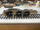
I built the bogie and wondered why I couldn't find the axle bearings. Well, I have also brought with me the Fowler tank to complete and I had accidentally put the bearings in with the bag of parts for that kit. That was not really a problem, until I discovered that I had also mixed up the supply of M2 nuts and 10mm M2 screws with the 8BA nuts and 10mm 8BA screws.......... So that was a frustrating hour spent sorting these. I will not be making that mistake again (I hope).
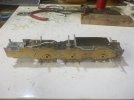
I decided that I ought to get some of the upper body structure formed before completing the frames. I need to get this right for the extensive pipe runs and I have got to the point on the frame assembly of locating the injectors and water valves. First part of the body assembly is the cab. It took me all weekend to get to the stages shown in these rather poor photos.
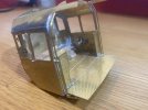
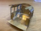
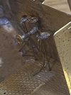
In case I haven't mentioned it before, the instructions leave something to be desired. The drawings and photos are very good but there are some key points that are not mentioned in the text. In the case of the cab assembly it is that there are two floor supports which need to be folded and positioned at an early stage. The written instructions do tell you to locate the cab rear before fitting the floor. I wasn't sure this would work, but it does.
Generally the fit of parts has been excellent. The exercise in origami that is the cab works quite well. But there are some parts in whitemetal that would be much better in brass. I think that the whitemetal casting in the last photo may be a slacking valve. Trying to locate this in place and then add three pipes and two control wheels was a real pita. If it had been brass then soldering would have been easy. I didn't want to risk soldering on such a small part so out came the Loctite 460.
I have built up the roof, side window frames and dragbeam assemblies. The windows probably need fitting after painting. I'll fit the roof now if the backhead will fit with it on.
Back to the loco: I managed to break all of the 0.5mm drills that I brought with me drilling out the various castings that need pipes attaching, or in the case of the cylinders, wire inserting to represent rivets. So it was back to the area next to Taipei Main Station, where in the same shop that I bought the M2 taps I was able to find a supply of small drill bits. So I bought up the stock of 6 0.5mm Japanese made drills at the equivalent of £1.50 each, which is about 50p cheaper that the German ones I get from Drill Service. I have to say that these Japanese ones are fantastic. Very sharp and cut quickly. I may have to go and buy up a few more of the small sizes before I return next month.
I built the bogie and wondered why I couldn't find the axle bearings. Well, I have also brought with me the Fowler tank to complete and I had accidentally put the bearings in with the bag of parts for that kit. That was not really a problem, until I discovered that I had also mixed up the supply of M2 nuts and 10mm M2 screws with the 8BA nuts and 10mm 8BA screws.......... So that was a frustrating hour spent sorting these. I will not be making that mistake again (I hope).
I decided that I ought to get some of the upper body structure formed before completing the frames. I need to get this right for the extensive pipe runs and I have got to the point on the frame assembly of locating the injectors and water valves. First part of the body assembly is the cab. It took me all weekend to get to the stages shown in these rather poor photos.


In case I haven't mentioned it before, the instructions leave something to be desired. The drawings and photos are very good but there are some key points that are not mentioned in the text. In the case of the cab assembly it is that there are two floor supports which need to be folded and positioned at an early stage. The written instructions do tell you to locate the cab rear before fitting the floor. I wasn't sure this would work, but it does.
Generally the fit of parts has been excellent. The exercise in origami that is the cab works quite well. But there are some parts in whitemetal that would be much better in brass. I think that the whitemetal casting in the last photo may be a slacking valve. Trying to locate this in place and then add three pipes and two control wheels was a real pita. If it had been brass then soldering would have been easy. I didn't want to risk soldering on such a small part so out came the Loctite 460.
I have built up the roof, side window frames and dragbeam assemblies. The windows probably need fitting after painting. I'll fit the roof now if the backhead will fit with it on.
Mea culpa!
I have just discovered that the two parts that I thought must be floor supports are instead the cab side lower extensions. Grrr! Replacements will have to be scratched. It seems that the floor is designed to be supported on the heads of the two screws that are used to secure the drawbar assembly.
Meanwhile work continues....
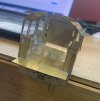
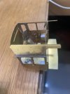
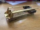


Getting on with the upper body structure was definitely a good idea. It showed that the cab outrigger supports were too wide. I am pleased to have found that out before doing the plumbing. I had to remove them and take nearly 1mm off them at the junction with the frames.
It also became clear that the cab side extension pieces would have filled a small gap above the outriggers. However, it’s not visible so I won’t tell anyone if you don’t.
I decided to fit some of the boiler and firebox details with the pieces still separate.
I have temporarily fitted the firebox, boiler and smokebox to see how it all goes together.

Yorkshire Dave
Western Thunderer
Still no decision on whether or not to get out the gas axe for the water scoop.
Could it be made detachable so the owner can clip in in or not?
Not easily. Fortunately the owner is happy to leave it.Could it be made detachable so the owner can clip in in or not?

