You are using an out of date browser. It may not display this or other websites correctly.
You should upgrade or use an alternative browser.
You should upgrade or use an alternative browser.
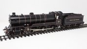
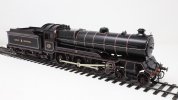
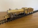
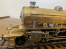
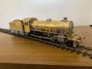
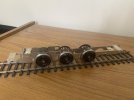
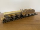
Something a bit different ( for me that is). Last year I was asked if I could complete a scratch built Britannia from an owner who, for medical reasons had had to stop work. It was substantially complete and I thought that it really only needed the plumbing adding. Closer inspection showed that it also needed front frame extensions, cab rear and some other bits too. Anyway, with the help of a bag full of Ragstone castings we have produced something that looks like a Brit, even if some of the detailing isn't quite right.
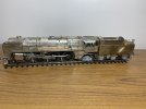
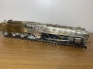
Next up are a couple of LNWR coaches - which may turn into 4 depending on how bored I get with the first two - and then the K1/1.
David


Next up are a couple of LNWR coaches - which may turn into 4 depending on how bored I get with the first two - and then the K1/1.
David
Thank you. I need to see if I have something chunkier for the exhaust steam pipe: it's 2.5mm copper. I may well have some suitable whitemetal casting from an LNER garratt kit that might suffice.The Britannia looks very nice. One thing that rather jumps out to me is the exhaust steam feed pipe to the exhaust injector on the RHS. This pipe was about 4.5" O/D - quite chunky, whereas that on the model looks like a normal (1.5 - 1.75 " O/D) steam pipe.
Dave.
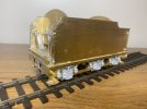
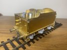
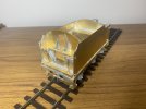
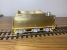
I decided that the brake and water scoop standards needed to be replaced so smuggled a pair from the Gladiator stores. I had already replaced the whitemetal brake and steam hoses with brass and replaced the axleboxes. I wish that I had done this before I used the Loctite 496 to glue them in place! Good stuff - first time I have used it but so far it is a plus. I am also beginning to use a lot more of 100 degree solder. Great for attaching whitemetal to brass and also makes a nice filler for tiny gaps.
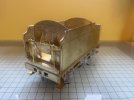

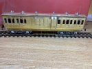
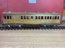
I decided that as Warren would be painting the two 42' coaches, he might as well have the 50' ones at the same time, so bumped them up the build list. They are both Gladiator (Northstar) vehicles, a D377 full brake and a D268 Third. I had a bit of a surprise with the third to find that the roof had not been pre-rolled. So I checked the other stock and none of those are done either. We have a delivery of etches promised for next week so I will gather all the flat roofs for a trip to Walsall Model Industries and get them to form the roof. I don't have a set of rollers long enough for the 50' and if I roll the 42' roofs then they end up more curved at the ends than the middle due to deflection in the rollers. I have looked at getting a big set, but it is just too much money.
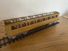
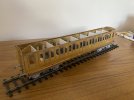
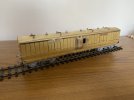
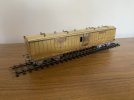
Nice looking coaches.
Now back to the K1/1. I will be using my Avonside chassis jig for the first time.
David


Nice looking coaches.
Now back to the K1/1. I will be using my Avonside chassis jig for the first time.
David
I forgot to take a photo before I wrapped it ready for Warren, but the corridor third has acquired a roof and is now ready for painting. I had a large delivery of etches last week and have been breaking them down and kit packing. The delivery includes a few coaches, so it will be off to Walsall this week to get them rolled to shape. being arc roof it isn't too difficult.
Having increased the Gladiator stocks by a couple of dozen kits ahead of the Kettering show, I have been able to get back to the K1/1. The customer wanted it with sprung hornblocks, so I have been using my Avonside jig for the first time. I have had it some time but with much of build of previous kits having been done in Taiwan I had had to rely on simpler alignment tools.
Anyway we have a nice free-rolling chassis.
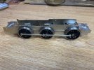
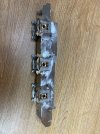
The springs have to be cut from the frames to get the axle bearings in. The kit helpfully provides some extension pieces to solder to the springs and some alignment holes in the frames to fit the springs. Unfortunately they are not in the right place, but the thought was there! The springs are retained with some 1/8" 14BA countersunk screws and a contribution or two to the swear box. The axle bearing keeps are held in by 1/8" 14BA hex headed screws.
I decided that the appearance would be improved by the addition of some cosmetic hornguides, kindly donated by the Gladiator stores. They are not an exact match to the Slater's inners, but I thought better than nothing.
I hope the build will proceed well: I now have the parts for the Fowler 2-6-4T and B16/2 (or B16/3) locos that will soon grace the Gladiator range and I want to do a test build before release. John Firminger's instructions are good so I am hoping that all will be straightforward. The new etches for the LNER O4/8 have just been ordered, so I am going to be a busy boy.
David
Having increased the Gladiator stocks by a couple of dozen kits ahead of the Kettering show, I have been able to get back to the K1/1. The customer wanted it with sprung hornblocks, so I have been using my Avonside jig for the first time. I have had it some time but with much of build of previous kits having been done in Taiwan I had had to rely on simpler alignment tools.
Anyway we have a nice free-rolling chassis.


The springs have to be cut from the frames to get the axle bearings in. The kit helpfully provides some extension pieces to solder to the springs and some alignment holes in the frames to fit the springs. Unfortunately they are not in the right place, but the thought was there! The springs are retained with some 1/8" 14BA countersunk screws and a contribution or two to the swear box. The axle bearing keeps are held in by 1/8" 14BA hex headed screws.
I decided that the appearance would be improved by the addition of some cosmetic hornguides, kindly donated by the Gladiator stores. They are not an exact match to the Slater's inners, but I thought better than nothing.
I hope the build will proceed well: I now have the parts for the Fowler 2-6-4T and B16/2 (or B16/3) locos that will soon grace the Gladiator range and I want to do a test build before release. John Firminger's instructions are good so I am hoping that all will be straightforward. The new etches for the LNER O4/8 have just been ordered, so I am going to be a busy boy.
David
A delivery of etches for the Gladiator stores resulted in a couple of days of kit packing, but I am now back to the K1/1. I decided to move onto the body to check for clearances etc for the motor-gearbox. Loads of space, which is good. It took some effort to get the boiler/firebox assembly square on the frames without distortion, but I got there in the end. The smokebox saddle was a problem. It is formed as a one piece etch - a rectangle with a hole in the middle. I could not get it to fit properly so initially chopped the rear cross piece off, and then, having located the boiler in place, splitting it side to side and fitting each side individually.
So now it is back to the frames.
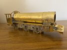
So now it is back to the frames.

No photos for now, but this has been a frustrating few days.
The kit supplies some nice lost wax castings for the crosshead and slidebars but I could not work out how they would fit together. The crosshead had a vertical flange at the top which completely interfered with the solid top of the slidebars. Eventually I realised that the slidebar casting was a replacement for the etched parts that are shown in the instructions. These etched parts would form slidebars with 4 legs: the flange at the top of the crosshead casting would slide between the upper two legs. So it was out with the saw and remove the flange. Then, after some fettling, I had a pair of crossheads/slidebars.
These were fitted to the detachable cylinder assembly which was then tried on the frames. Disaster! I have used Premier components coupling rods. These are nice, but thick. There is absolutely no clearance between the coupling rod - let alone any fixing - and the slidebars. So I could either move the cylinders out or replace the coupling rods. I decided to replace the coupling rods with the etched ones from the kit and pray that I can get the centres identical to the Premier ones and not have to relocate the axleboxes.
I have done one side already and I think it will work. The chassis still rolls nicely with one side etched rods and the other the Premier ones. By omitting the boss on the leading coupling rod end and using a threaded crankpin bush as a fixing it might just work out. Fingers crossed.
Last edited:
I struck lucky: the etched rods were at the same centres as the milled ones, so with a minimal amount of adjustment I once again had a free rolling chassis. Also moving smoothly when motored. It was still a real pain to get clearance behind the cylinders. I omitted the coupling rod boss and thinned the head of the 12BA tapped crankpin bush, then there is clearance: just.
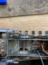
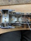
So it is now looking like this:
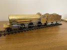


So it is now looking like this:

Progress: chassis now ready for painting, but before I do I will put the motor back and just check that it still drives properly. Should be no problem as all rolls smoothly without. The left rear crankpin is waiting on the speedo drive crank which will be fitted once the speedo bracket is attached to the body.
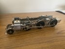
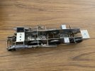
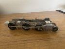
A couple of learning points for anyone else going to build this. The instructions say to fit the slidebars to the cylinders using the motion bracket as a guide. later the instructions point out that you may need to remove material from the bottom of the motion bracket. You will need to file the motion bracket. So set up the slidebars so that the piston rod, if extended, would line up with the centre driving axle and adjust the motion bracket to suit.
The motion bracket is also too wide and will interfere with the valances. You need to file the top for clearance. If you solder the motion bracket to the slidebars but not to the frames, and make the weighshaft two pieces that just pop into the frames, then by removing the return crank from teh centre crankpin, the whole valvegear assembly can be lifted out.
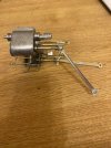
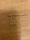
There are a number of rivets supplied for valve gear assembly. I preferred not to use these. Most of the joints are forked, so wire pins soldered in place are a better alternative. I used 12BA screws to attach the union link to the dropper on the crosshead as the hole in the crosshead is large and I use a countersunk 12BA screw in the return crank soldered into the eccentric rod. I still need to file the head of the screw in the union link.
Now back to the body.
Four coaches and a loco! Yes, I am pleased with that.I'd call that a good six weeks.
David
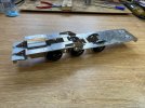
With the basic frames complete, I have started on the body work.
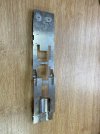
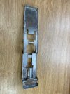
The footplate is in 3 sections, two of which require bending to shape. I used the valances as a template for the bends. The saddle was a bit tricky, but so far it has gone together well.
Hoping to get the main upper works in place tomorrow.
The footplate is in 3 sections, two of which require bending to shape. I used the valances as a template for the bends. The saddle was a bit tricky, but so far it has gone together well.


Hoping to get the main upper works in place tomorrow.

