Finescale - of a sort?!

Peter Insole

Western Thunderer
Mmm, indeed Tim, you now have me wondering about the possibility of sieving out the mucky fines, and perhaps crushing the lumpier char from our domestic grate, then using a hair spray or artists' fixative to lightly dust and it tack down?

I'm not sure about the old, faithful, but rather evil "spray mount", as it spreads it's gooey mess too far about, so it's probably about time I started actually reading the bits about scenic stuff eh?!

Pete.
 

Peter Insole

Western Thunderer
Apart from the "char" issue, the smokebox interior is otherwise done, but there are still plenty of other jobs to do while the boiler is out of the frames.

I really could not put off getting the cladding sorted any longer, especially as the new steam brake piping hugs the firebox end profile quite closely, and I now know exactly where the main steam pipe and blast pipe fixing bolts come through the base of the smokebox.

Inevitably a snag has arisen with those brake feed and exhaust pipes though, and that is entirely a result of my own stubborn determination to keep all the fittings and associated plumbing attached solely to the boiler - in such a way that it will always be possible to separate it from the underframes without having to disconnect a multitude of disparate joints! Fortunately, the original design of the loco has been beneficial in all but two features, namely, the aforementioned brake pipes, one of which has it's union and nut projecting, and both dropping down loosely through holes in the right hand running plate, while the left hand saddle tank balance pipe rather awkwardly reaches the well tank below via a simple notch in the opposite plate!

Leaving aside the latter problem for the moment, the relevant issue of the brake pipes is their small diameter, and the distance from the valve (on the top manifold) to their locating holes in the plate. Lifting the boiler would be easy, but making sure that two slender copper pipes are perfectly aligned - along with ten boiler flange studs - plus ensuring that the motor drive shaft slot engages correctly in the gearbox - and all at the same moment while attempting to maintain a grip on a surprisingly weighty, cylindrical object when putting it back!

There is (supposedly) an answer to everything, but the available solutions are not always entirely acceptable! I have been thinking along the lines of pressing the pipes into actual contact with the boiler cladding for the larger part of the circumference, and using some (almost) hidden, copper pins, drilled and soldered into the back of the pipes, and thence pressed thro the barrel, hoping that such things will only be apparent by very close observation.(?) I am still not sure though!

Whatever approach I finally choose, and soon at that, the cladding must be complete, fully painted and thoroughly varnished beforehand... so off I jolly well need to go...

huSAM_yy0856.JPG

I doubt that I will ever learn to make life easy for myself - and this task proves it at least twice over again!

Having now (very) permanently fitted the base section of the saddle tank to the boiler barrel means that the cladding sheets have to butt up very tightly under the bottom edge - rather than passing underneath as in the prototype. Careful cutting is not so much the problem here, but for my own comfort, integrity of the glue joint is! It would be such a shame, and downright awkward if the cladding starts to come away along that edge - and end up naturally ballooning outwards? If I had thought more clearly about it at the time, I could easily have cut a shallow rebate on the inner face of the timber rails prior to assembly - but it is all solidly glued and screwed in place now! Some fine tacks, driven well down with a nail punch and covered over with filler will have to suffice.

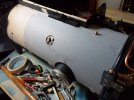
A result of the original engines being specifically set up (as recently confirmed by other researchers) in the first place for walking control, (horse shunting style driving) all the fittings are on, or readily accessible to the left side, which means that there are several more odd size and shaped holes to cut out in the sheets here. I thought it wise to trim and tape tracing paper on first to ensure every cut would be in the right place:
huSAM_yy0857.JPGhuSAM_yy0859.JPG
huSAM_yy0861.JPG

At this point I should mention my second problem:

When I initially made the boiler from a postal tube I knew that the cardboard would have to remain naked for a fair while - at least until some other fittings had been completed. For the sake giving it a modicum of weatherproofing, as well as for appearance, I sprayed it with some automotive type, satin black paint. Readers may recall my intention to use "reclaimed", and apparently nefariously acquired steel sheet for the clothing, but I have since changed my mind, and decided to utilise beautifully fine grained and flexible 0.4mm birch ply instead. I am rather glad that I did from the point of view of cutting out the shapes, but far less so when considering adhesives!

Metal sheet could have been rolled, and thus to a degree, in keeping it's shape would be easier to retain in place, whereas the wood has to be firmly stuck down! Doing so on a pre-painted, and therefore slightly impervious surface, would require some type of "impact" adhesive.

No thanks!

Wood glue spread on wood, or a fibrous, wood based material is partially absorbed and effectively sucks the surfaces smoothly together as it cures... as well as providing some wriggling before it sets.

There was only one thing I could do about it...

huSAM_yy0864.JPG

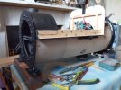
It was tedious... dreadfully messy... and terribly spouse annoying... but fortunately practical to peel off the outer, brown paper covering layer - partly aided by the bonding effect of hardened paint!

Unfortunately, it didn't all come off in nice big chunks like the above image though... and I didn't receive much in the way of encouragement when "bits" started migrating either!

huSAM_yy0862.JPG

It does look nice and smooth already...
huSAM_yy0867.JPGhuSAM_yy0868.JPG

...and hopefully will look even better once fully primed, filled and covered in several coats of gloss!

It is a pity that the LYR never lined the boiler bands on any of these engines since they were rebuilt in the early 1900's... but then again, nowadays I am ever so slightly relieved about that too!!

Pete.
 
Last edited:

Crimson Rambler

Western Thunderer
Apologies for coming to the party late but the reason why a loop, pig tail etc is fitted in the line to a steam pressure guage is for accuracy.

The loop acts as a condensation trap and was designed to retain water within it at all times. This water was thus remained at ambient temperature but under boiler pressure.

Internally the traditional pressure gauge contains a short length of oval section tube that is bent in the form of an arc. One end of the tube is in effect open to the boiler while the other end is closed. When subjected to internal pressure the tube tries to straighten which results in a small movement which via a toothed quadrant acting on a pinion rotates the latter's spindle and thereby moves the pointer.

If steam is allowed to enter the instrument directly its high temperature expands the tube thereby giving additional movement to the pointer and thus results in a high reading.


Crimson Rambler
 

Peter Insole

Western Thunderer
Thank you Crimson Rambler for taking the time and trouble to reply, and to everyone else who has contributed to such an interesting debate!

Moving on, I'm afraid that the next two progress images are not terribly pretty, as while I am waiting for a delivery from Humbrol I have been stretching out the last drops of matt black from a pair of remaining 14ml tinlets - and at the same time using an old brush to do it, rather than spoil a nice new one reserved for the gloss top coats!

huSAM_yy0872.JPGhuSAM_yy0873.JPG

I must confess that making up detailed boiler band brackets is another example of (almost) pointlessness, as once the boiler is back in the frames the blackened items are almost invisible in the narrow gap between the cladding, running plates and various fittings mounted thereon!

Examination of both surviving locomotives reveal a mish-mash of designs that are presumably the result of various replacements over time, but are all sturdily forged from either iron or steel. When considering a potential vulnerability of these little dangly bits when lifting and laying down the model boiler for maintenance, I had intended to make mine from metal also, but subsequently decided that the additional effort of sourcing suitable material, and then working with it was probably not really worthwhile for a purely decorative, non-functional feature. A much cheaper, quicker and easier use of plywood strips glued at right angles could still too easily be snapped off though, so the eagle eyed amongst you might observe my sneaky application of small, reinforcing split-pins, pinched over the set screw threads and set deep with cyano into the barrel?!

The whole assembly is, as mentioned, barely visible, but I do take comfort that this particularly naughty solution is at least completely hidden in the space between the brackets when the loco is upright and in running order anyway!

Pete.
 

Peter Insole

Western Thunderer
Thank you Tim. I know how acutely self critical I can be immediately after having spent any length of time working on details... but have to remind myself that such concerns are mostly forgotten when seen in the whole - and usually at least as soon as the next task is commenced!

It might seem peculiar, but much later I find myself wondering how on earth I actually managed to do... or rather "get away with" doing any of it!

Pete.
 

Peter Insole

Western Thunderer
It might be surprising to some, but this is the bit I least enjoy nowadays: Paintbrushes and me have never particularly been friends, and the slightly strained relationship has definitely soured even further since "retirement"!

Still, needs must and all that, so if I really desire to get the engine actually finished; the horrible little sticks with hairy bits just have to be wetted and wielded once again..!

huSAM_yy0878.JPG

Two coats of matt, the first one thinned to act as a primer had successfully hidden the unwanted wood grain, and the second of at least four coats of gloss have now gone on.

huSAM_yy0879.JPGhuSAM_yy0881.JPG

I will have to give it an abrasive cut to remove the worst of the accumulating dust and fluff before varnishing, but I am not at all worried about knocking back the brush strokes, or even the occasional dribble - indeed on the contrary, I want them to be there!

This is after all a large model of a very small engine, and although a perfectly smooth, mirror like finish would look lovely and professional, it would in reality be totally wrong!

Pete.
 

Peter Insole

Western Thunderer
Thank you Brian! Although exhibitions have always scared the living daylights out of me, (a very longstanding phobia I'm afraid) I do hope one day to have the opportunity to bring it to a show - along with a section of portable track, and where you (and other good friends) could have a go on the regulator!

At least I wouldn't have to worry about a boiler certificate for this one?!

Pete.
 

Peter Insole

Western Thunderer
While waiting for the top coats of gloss on the boiler cladding to thoroughly harden before varnishing, and most of the plumbing is off the loco, I thought it would be a good idea to get all the various pipe fittings finally finished!

No small task as it happens! I have been taking photographs but not got around to posting the results, so a bit of catch up is in order now:

Starting with the odd little injector; our trip earlier this year to Tywyn provided an interesting comparison, and amongst other things revealed the missing link - or rather the absent water cock lever of "Wren"!

hrbhiSAM_3068.JPGhrSAM_yy0074.JPGhrSAM_yy0075.JPG

I was curious to observe a slight variation in the body design, including a faint trace of the first and last few letters of what was presumably "Gresham & Craven" inscribed round the circumference of the steam inlet flange, but the biggest surprise was that the handle is very clearly a steel casting, (or forging) although perhaps less so the valve spindle itself, as close inspection confirmed that to be bronze.

Relieved at the prospect of being able to cut a new valve spindle in nice, workable CZ... whatever the number (?) brass rod, I ditched the "temporarily lashed-up" - although admittedly quite pretty (!) lever of my own earlier making, to replace it with something a bit more functional and accurate in appearance:

huSAM_yy0883.JPGhuSAM_yy0886.JPG

I made the squared shaft as close to scale as possible, as I was keen to include the distinctive centre point and slot arrangement on the end.

Incidentally, the genuine valve should be a tapered, self-aligning, gas-tight fitting of course, but as the function of an injector relies entirely upon the principal of steam condensing when it "hits" the water, thus creating a vacuum within the chamber to operate, any possibility of air being drawn in through a worn or grooved valve would have to be avoided at all costs. Frequent checks and re-boring when necessary should, I am given to understand, be a routine practice.

Having decided to create the lever from sections of stainless steel, (from various and readily obtainable coach bolts) for the practical reasons of both avoiding corrosion and mimicking the highly polished finish of regularly handled items, made for some particularly hard work!

I bottled it a bit when it came to the hub boss, and accepted a compromise on the external diameter. Cutting such a long square bore right through such a hard material didn't leave much room for grip in the vice - or error come to that! I could have mounted and then spun off the excess to finish, but realised that quite apart from any other difficulties arising, I had more than enough exercise for that day already, so left it well alone!

huSAM_yy0889.JPGhuSAM_yy0899.JPGhuSAM_yy0902.JPG

I did a little bit more trimming and cleaning up of the square end and details later, but although it is not quite right, I still hope it goes some way towards capturing the "character" of the thing?

Pete.
 

Peter Insole

Western Thunderer
Thank you Fitzroy! The task of constantly trying to work out how on earth to make something that not only looks reasonably representative, but works in some way or other, can frequently be a bit of a trial, but I am led to believe that the activity is good for brain health! My good lady wife might beg to differ at times however?! I must admit that the prospect of completing a collection of "twinkly" brass, copper and steel brightwork assembled on a lovely glossy black background is one of the things keeping me motivated... but it does come at the price of a worryingly deteriorating credit score in the domestic department though! :(

I had better crack on then... but not before another quick update to complete this part of the injector tale:

huSAM_yy0905.JPG

I have at last got rid of the (also temporary) white plastic gasket on the steam entry port flange!

A small portion of recently acquired black Plastikard (for yet another half started project!) was "sacrificed" - well, pinched more like, but the result is slightly better looking, albeit if just a touch on the the bulky side?!

huSAM_yy0906.JPGhuSAM_yy0909.JPG

When I originally made the flanges up I committed an unfortunate error: The three holes for studs were the right diameter for tapping to an appropriate M4 size, but I drilled them slightly too close to the outside. The nuts would clear the pipe well enough, but end up overlapping the rim!

For want of a solution, the engine has been running for absolutely yonks with a "round tuit" screw and some cocktail stick "treenails" holding the fittings together, so getting that sorted was a priority.

Being somewhat unwilling to source more brass of the correct thickness, and definitely having no desire to remake the flanges anyway, (!) I did a bit of jiggery-pokery with some brass rod and jolly Loctite to reach a compromise set of M3 studs instead! Admittedly, the silly little nuts are of a rather slender, undernourished appearance, but they will hold it firmly together until I can find some slightly beefier alternatives (?)!

I had also made a dreadful boo-boo with the centre hole in the steam supply valve handwheel:

My original intention had been to correctly mount the wheel on a squared shaft, but almost immediately realised that I had drilled the hole too big - and that with the keyed section now having to be the same size as the shaft, it would not allow the wheel boss to lodge at any point. Besides that, the cut corners would show around the locking nut as well!

After much cogitation over many moons, I eventually decided that I might get away with tapping and threading both the awkward hole and spindle in two, reducing sizes, and relying mainly on pressure applied to the lock nut - although there is a slight shoulder available for the wheel boss to press against:

huSAM_yy0913.JPGhuSAM_yy0915.JPG

Messy, but ultimately successful... so far at least anyway.

If it does ever show a tendency to work loose in service, I can always apply some "permanent" Loctite - although I would rather not if I can possibly avoid it!

huSAM_yy0917.JPGhuSAM_yy0919.JPG

One thing that has been bothering me, and that applies to all the various valve handles, is the amount of "slop" in both the male and female threaded and plain bores.

I cannot see any viable means of fitting O-rings or gaskets of one description or other to provide a restrictive "feel" anywhere. I had considered inserting small coil springs into the valve bodies to apply some outward pressure on the threads or stops, but feared they could either become "bound" if over tightened, or, out of the necessity of avoiding liquid lubricants, become invisibly corroded within the chambers?

Then I remembered the old trick of using candle wax for sticky wooden draw runners. As far as I am aware, unlike regular animal, vegetable or mineral grease, there should be no problem of fluids separating and leeching out into the surrounding timbers or indeed any delicate contents, plus the stuff potentially lasts for centuries, so I considered it might be worth trying?

I am happy, nay delighted to report that the resulting effect provides just the right amount of smoothness and yet stiffness in operation to be absolutely perfect for giving the impression of a properly ground valve working against a back pressure of live steam or weight of water!

Sadly, the only thing absent now will be the "phwwhhh" or "yarooo" response to extreme temperature on contact!!

Pete.
 
Last edited:

Peter Insole

Western Thunderer
Thanks Tim T! If "proper" means the extensive use of files and big hammers to make lots of " minor adjustments to fit", then I'm really happy with that compliment! ;)

Pete.

edit: I must remember to resist the temptation to polish, and add a few more deliberate "clouts" here and there for a prototypical effect!
 
Last edited:

Peter Insole

Western Thunderer
It is a good feeling being able to see all the various footplate fittings nearing completion. Getting the engine up and running, perhaps too soon, removed some of the impetus to properly finish things off!

I have noticed that there were originally two types of valve on this engine, with the injector water cock, blower and pressure gauge isolating cock being of the straight through variety, with a lock nut outside and opposite the lever, whilst the water level gauge isolating and blowdown cocks are enclosed, with the valve retained at the top by a hollow screw. According to the relevant drawings, and the remaining part of Horwich "Wren", the steam brake valve is also of the latter style, whereas "Dot" at Tywyn has what appears to be a replacement, straight through version. The anomaly had me confused at first, and was to come back and haunt me after I had decided to drill the valve body all the way down the centre!

One advantage of my error however was being able to add a longer tail on the valve spindle, below the retaining flange, to hopefully act as a guide and add some protection from excessive, or accidentally applied leverage:

huSAM_yy0922.JPG
huSAM_yy0923.JPG

Awkwardly, I cut the spindle thread a couple of turns too many, leaving the shoulder a touch too close to the retaining screw, which will mean that the lever will end up slightly low on the body.

I did shave off a bit more of the screw later, but still didn't have quite enough to make up the difference.

huSAM_yy0926.JPG

In the above view, the spindle has dropped down by gravity into the valve body - but will be held up in the operating position by spacing washers between the screw and lever.

After much thought, and still being unable to fully satisfy myself of the original, genuine material, I finally elected to be done with the issue and make the lever and handle from steel! I didn't particularly fancy shaping the lever with a raised boss at one end from solid bar either, preferring a simpler, soldering solution, so opted for mild steel there, while the more frequently touched handle should be (as ever) in stainless.

huSAM_yy0928.JPGhuSAM_yy0930.JPG

Thinking about both the vulnerability of a sticky-out handle on a slender (ish) stalk, and also the sheer effort involved in wrangling unyielding stainless, I opted for the short, stubby version of the handle seen clearly in the cropped 1930's photo of "Midget", (post #661) and similarly carried by other members of the class at various times.

huSAM_yy0934.JPGhuSAM_yy0935.JPG

When the completed unit was put back on the engine, the lever and handle do look a bit small... although the valve body still seems to be OK. I had been careful to prepare correctly scaled drawings, but they are based on an earlier (?) pattern. I now suspect that my lever and "stubby" handle is in proportion with itself, but is slightly reduced overall.

huSAM_yy0945.JPG

I take some comfort in the thought that the wee handle is only big enough for (full size driver's) finger and thumb operation... so there is mildly less chance of the entire valve being inadvertently wrenched from the manifold?!

huSAM_yy0950.JPGhuSAM_yy0951.JPGhuSAM_yy0954.JPG

I nearly forgot to explain the "haunting":

As described previously, I have found that candle wax is ideal for providing a degree of "feel" to the levers, and remains contained within the valve bodies where there are handles, shoulders, lock nuts or enclosed ends. In a moment of confusion had drilled all the way through the barrel with this one, but then realised it should only have a blank bottom. The wax would simply get squeezed out every time the lever is moved!

The trouble I perceived was that all the previous soldering had been done with the same temperature stuff, so filling the hole would have to be by mechanical means: I selected an oversize piece of brass rod, shaped it down and rivetted it in place by thoroughly peening it with a nail punch to form a shallow rivet. Fine and sound until I filled the chamber with wax, and then tightened down the screw.

I completely failed to appreciate the sheer power of hydraulics!

There was a squidgy pop, and I ended up with a thin, parallel stalk of wax protruding below - and a little brass circle stuck on the end! My clumsy attempt at retrieval meant a total loss to the carpet monster... so despite the late hour, I crossly rushed down to the cellar, grabbed a tap and cut a thread in the hole, found a small offcut section of previously threaded, scrap brass rod, then drove it in until absolutely tight before cutting and filing away the excess.

Something that I really should have done in the first blooming place!

Pete.
 
Top