Prototype Ex-GER Y14 (LNER J15) preserved at the North Norfolk Railway

Richard Gawler

Western Thunderer
Col this is perfect.

Not that I know which pipe is the water feed but because can see an electrical connection from my model tender to loco, placed level with the loco axles, should blend in fine.

They say every day's a school day - this is the first clear photo of this end of a steam loco I have ever seen. Even the construction of the steps is clear to see.
 

Richard Gawler

Western Thunderer
I am moving on to building my Y14 and I would much appreciate advice on the boiler especially boiler bands . . .

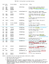
The GER built three sets of batches on which I could base my model (see the attachment at the end of this post):
  • R23, T23, Y23, U25, Y25, running numbers 845 to 894 (1889 - 1890) : 3 ring boiler with flat grate (needs chassis modifications)
  • L28, N28, P28, running numbers 895 to 924 (1891) : 3 ring boiler with sloped grate
  • S28, X28 running numbers 925 to 945 (1891 - 1892) : 2 ring boiler with sloped grate
The second and third sets of batches are better for me because the Connoisseur kit represents a model with a sloped grate.

DSC_1093.jpg
This is the boiler from the kit, supplied pre-rolled.

I think this represents a boiler from the third of these designs, that is a 2 ring boiler with a sloping grate. Because the holes for the dome and clack valves are in a forward position.

Please (supposing I have got this right so far) could someone tell me whether such a boiler had boiler bands?

I thought I knew what I was going to build and then someone told me, locomotive number 930 (the one built in a record time) did not have boiler bands. This implies, I might need to have the boiler re-rolled inside out. Then again, if the contemporary three-ring boilers did have boiler bands, and the etched lines are in the correct place, it would be easier for me to move the dome and clack valves.

The attachment is a detailed list of the batches and their variations, have taken from an article
Brooks, Lyn D.
T. W. WORSDELL'S CLASS Y14 0-6-0 (LNER CLASS J-15)
Great Eastern Journal February 1983

and the horizontal blue lines marked enclose the batches I want to choose for my model.
 

Attachments

  • build variations markup.png
    build variations markup.png
    354.1 KB · Views: 7
Last edited:

Eastsidepilot

Western Thunderer
Richard,
Engines built before 1891 had a Dia. No.31 boiler which could only be used on J15's, these had a level grate. Post 1891 the firebox was given a sloping grate and these boilers became Dia. No.32 These could also be used on E4 & F3's.
The LNER then altered 39 of the pre 1891 engines frames to take the Dia. No.32 boilers.

The number of boiler rings denotes the way the actual boiler is made up and has nothing to do with the cladding.

They are all fitted with boiler bands as is any steam loco is and the Connoisseur kit boiler tube can be used although it's not 100% accurate, dia. wise. The boiler fitting's were always in the same positions.
The boiler band at the front of the firebox should wrap around the boiler and not down the side of the firebox.

The boiler bands in model form are usually way to thick, I replace them using brass shim cut with a steel straight edge and a Stanley knife. A real boiler band is only about 3/8" so use something like 0.005" brass.

Col.
 
Last edited:

Dog Star

Western Thunderer
A real boiler band is only about 3/8" so use something like 0.005" brass.
I do not know which locos are being referenced by Colin so I am not able to comment upon Colin's statement that real boiler bands are about 3/8" thick. When restoring GWR locos at Didcot in the 1970s and 80s the bands which secured the cleating were circa 16swg thick (so 0.064" prototype / 0.0015" in 7mm scale).
 

Richard Gawler

Western Thunderer
Col. thank you so much. You have let me separate the facts from a mire of information I received from someone with a lot of enthusiasm but perhaps relatively little knowledge.

I do not know which locos are being referenced by Colin so I am not able to comment upon Colin's statement that real boiler bands are about 3/8" thick. When restoring GWR locos at Didcot in the 1970s and 80s the bands which secured the cleating were circa 16swg thick (so 0.064" prototype / 0.0015" in 7mm scale).

When I come to do the boiler bands on my model, I will try to use the thinnest material I can obtain and have the ability to handle.

I will need to fill the half-etched line just behind the front of the firebox so I can put the boiler band in its proper place around the boiler and not down the front of the firebox.
 

Eastsidepilot

Western Thunderer
I do not know which locos are being referenced by Colin so I am not able to comment upon Colin's statement that real boiler bands are about 3/8" thick. When restoring GWR locos at Didcot in the 1970s and 80s the bands which secured the cleating were circa 16swg thick (so 0.064" prototype / 0.0015" in 7mm scale).
My mistake, your right it should be about 1/16" not 3/8" I was probably thinking of the width of the band which is 3 " :rolleyes:

Col.
 

Richard Gawler

Western Thunderer
I have bought myself a copy of Yeadon volume 35 (LNER J14 and J15), this book has a mixture of wonderful photographs and some narrative which I am finding just about impossible to penetrate.

From the introduction,
"The former, which actually came after the latter, was not as successful as its predecessor ..."

:headbang:

Thinking about whether to attach balance weights onto the wheels of my model of an 1891 engine, a caption on page 13 reads,
"The early Stratford built engines, Nos.7610 to 7639, had cast iron wheels, and only from 1899 were wheels balanced"

Cross-checking this claim against Brooks, I suspect this caption is hiding three distinct facts:
1) The first batches of Stratford built engines (these included numbers 7610 to 7639) had cast iron wheels.
2) All of the engines built at Stratford up to and including 1892 were built with unbalanced wheels.
3) The later engines (1899 onwards) received balanced wheels when new.


and possibly (but without any great conviction from me at the moment),
4) Some or all of the engines built with unbalanced wheels did receive balanced wheels later, but this happened from 1899 onwards.

Please, does this sound fair? I know it easy enough for me to leave the balance weights off and add them later but if I could learn how to clear up just one ambiguity it might leave me feeling I had a chance of making a historically correct model.
 

Eastsidepilot

Western Thunderer
Don't know if you have a specific loco number for your model but finding out if it had balanced wheels at a specific date or not will be almost impossible to know without photographic evidence, looking at the Yeadon's book page 3, photo shows 627 in L&NER livery without balanced wheels, top photo on page 13, 7833 has un-balanced wheels in '37 as does 886 probably in the '20's going by the lettering and below that 7621 has still not had it's wheels changed in LNER ownership.
Another photographic example, page 14, is 627 again, a Sharp Stuart built, still without balanced wheels in '23.

Col.
 

Richard Gawler

Western Thunderer
Thanks Col. You are better at finding things in Yeadon than me . . .

I am trying to represent a loco from 1891 or 1892, built without brakes (only a tender brake) and still in its original condition. The idea is to show how my imaginery branch might have looked during the last ten years of the 19th century.

Brooks (Great Eastern Journal, October 1983) writes,
". . . the original Stratford Engines were
hand-braked only, whereas the Sharp, Stewart engines had
steam brakes. Between 1896 and 1901 all of the earlier engines
were given steam brakes . . . "


I reckon, these locos received a steam brake well before they received balanced wheels. I can put my balance weight etches into the bag of unused parts.

Ideally I would find a loco which received its brakes in 1901 but this is going to be difficult. I might just leave my model unnumbered. I have done this on other layouts in other scales; if the railway is a fiction then perhaps the identity of the loco should stay unspecific.
 
Last edited:

Richard Gawler

Western Thunderer
There is a gap in the original numbering of the Y14s between number 934 at the end of batch S28 and number 936 at the start of batch X28.

So 935 would be a good number for me unless it transpires the GER used it for some other loco. The only example of the class to work the Langford to Heybridge branch. If someone tells me the model is wrong in some way or another I can invite them to show me a photo of the prototype so I can try to get things sorted out :cool:
 

Lyndhurstman

Western Thunderer
There is a gap in the original numbering of the Y14s between number 934 at the end of batch S28 and number 936 at the start of batch X28.

So 935 would be a good number for me unless it transpires the GER used it for some other loco. The only example of the class to work the Langford to Heybridge branch. If someone tells me the model is wrong in some way or another I can invite them to show me a photo of the prototype so I can try to get things sorted out :cool:

Hello @Richard Gawler

“D&P 203 was issued for the construction of the experimental two-cylinder compound Y14 class 0-6-0 No. 127 in 1887. Officially, the engine was referred to as the "No. 127 Class" on the locomotive diagrams. In the mid-1890s it was renumbered 935, and presumably became the "No. 935 Class". However, it was shortly afterwards rebuilt with simple cylinders of the same pattern as those used on the N31 class 0-6-0s and assimilated to that class.”

N31s became LNER J14, I believe.


Cheers

Jan
 

Richard Gawler

Western Thunderer
Loco no.127 would make an unusual subject for a model, as long as the layout is pre-1914. Not this time for me, but perhaps it could be created from a kit for a J15.
 
Last edited:

Richard Gawler

Western Thunderer
P1040374.jpg

roof detail.jpg

I wonder, do we know whether the roof of the cab on 564 is representative of the fitment on locos as they were built with the original low cab?

I suppose I am surprised there is no rainstrip at each side. Then again it does look fairly simple to represent on a model.

One day I am going to have to make the roof for my model Y14. I guess I will omit the planking (no idea how to do it) so I am looking towards a rectangle of brass and some kind of shaped/curved brace underneath near the back.
 
Last edited:

Osgood

Western Thunderer
As you are probably aware from info available (M&GN Soc. website), the original shallow wood roof was replaced by LNER in 1933 with the higher pitched roof, in which condition it ran early in preservation (see below, 2002 - photo from MSLR's website).

I don't when in recent years it was put back to early style, but I would be surprised if they did not have access to the original drawings by then, and so imagine it would have built exactly as per original - if I were doing the job, and if it had rain strips, I would have installed them.
If you'd like I can give you a contact who can put you on to the NNR's Chief Engineer who will no doubt have the answer.
J15-Brockford-2002.jpeg
 
Last edited:

Eastsidepilot

Western Thunderer
Richard,
As Tony says the cab roof is much as the original when first built, judging by the photo's in Yeadon's book it seems that they did not have rain strips in the early days but gained them in later GER days before the LNER.
Some details in the attached pdf's show early roofs had a strip or band over the top also check out detail no.28 in the Loco Details file.

Once again try and find photographic evidence of your particular loco.

Col.
 

Attachments

  • LG017 Y14 (J15) 0-6-0s 7mm.pdf
    1.9 MB · Views: 27
  • LG023 Loco Details (1).pdf
    1.4 MB · Views: 18

Richard Gawler

Western Thunderer
I have plenty of photos of Y14s in their modified conditions, and drawings too; but no clear usable photos of locos built in the 1890s and still in their as-built state. Which is what I want to help portray the 1890s on my layout. I feel, ignorance should be bliss; I am settled on building on a loco from batch S28 or X28 (running numbers 925 to 945 except 935) and if I choose my prototype from this range by rolling a die then surely no-one will come up with a photo to show how wrong I have got things.

Thank you Col. for the drawings and LG023 especially. I have been studying LG017 on and off since last summer but LG023 is new to me and I doubt I would have found it on my own.
 
Top