Prototype Ex-GER Y14 (LNER J15) preserved at the North Norfolk Railway

Richard Gawler

Western Thunderer
Col, I cannot see an angle iron on the end views but I can see how my coping ought to look - I will use the castings from the kit and keep their strapping detail.

I can also see, my top-down photos of the top of the tender of 564 will not help me at all here. The coping on this preserved tender has been constructed in a different way.
 

Peter Insole

Western Thunderer
Just to confirm that there should be joints on the tender flares. The overhaul was a "professional" contracted out job - and not the result of hours' worth of dedicated work! ;)

There is a whole lot of brand spanking new, but (necessary) cost cutting welding up jobs all over the place on that engine now!

Pete.

Edit and an admission: I have just checked, and the welded tender was done earlier by the "dedicated" team! :rolleyes:
 
Last edited:

Richard Gawler

Western Thunderer
Okay!

I am sure, what I have seen with my own eyes is the least useful resource I have for my Y14 project. Everything else is better, be it other people's models, the GERS drawings, photos of the locomotives before preservation (even as modified by the GER, LNER and BR), and of course the accounts of the locomotives by Brooks.

On the bright side, I feel I have enough prototype information to tackle a passable 1889/90 tender. I'll save my doubts on the loco itself for another day :)
 

Eastsidepilot

Western Thunderer
Okay!

I am sure, what I have seen with my own eyes is the least useful resource I have for my Y14 project. Everything else is better, be it other people's models, the GERS drawings, photos of the locomotives before preservation (even as modified by the GER, LNER and BR), and of course the accounts of the locomotives by Brooks.

On the bright side, I feel I have enough prototype information to tackle a passable 1889/90 tender. I'll save my doubts on the loco itself for another day :)
I'm sure you'll end up with a good model Richard :thumbs:

Col.
 

simond

Western Thunderer
It is an excellent book, there’s a few more from the same pen - chassis, track & whitemetal locos.

All very much formative reading for my modelling.
 

Arun Sharma

Western Thunderer
This is a bit poignant but at the moment I am half way through "Etched Loco Construction" by Iain Rice. This is extremely readable and informative and is building well on my experiences of building "Nellie the crane tank". This book is over 30 years old but the advice still rings true.
It is an excellent book, there’s a few more from the same pen - chassis, track & whitemetal locos.

All very much formative reading for my modelling.
Agreed - as are Ian's DVDs on wagon building
 

Richard Gawler

Western Thunderer
We have a few technologies new since Iain wrote his book on loco construction, but not many. I am having my first go with some 100 degree solder to put the copings onto my Y14 tender.

Yesterday I built myself a variable mains power unit for my soldering iron, using a dimmer switch and a 13A socket. The 100 degree solder reminds my of the T1000 in Terminator 2. I think Mr Spock would say, its solder Jim, but not as we know it. It is very soft, and very easy to clean up, and goes onto bare brass without tinning first.

This post probably ought to be on my workbench topic but it follows on better here.
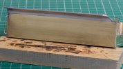
DSC_0845.jpg
This is the worse side of the side of the job, photographed rather carefully from a suitably flattering angle.

DSC_0840.jpg
This is the same work, with the lighting altered to show how I am really getting on.

My own feeling is, I cannot expect to model a scale 1/4 inch overhang at the bottom of the coping (because of my present abilities in 7mm scale) but I might create a horizontal line on the model to imply the overhang is there. Even draw one! And I am wondering what to do next. I have already had two goes at adding more solder and then cleaning it away again. I wonder if there is a filler I could use, to wipe into the gap nearest the camera? Perhaps a fine surface filler used by car body shops?

At the end of the day, I will be happy if I have a model good enough to take a satin paint dinish not a full gloss, Though there is a nagging perfectionist inside, and usually not far from the surface.
 

Eastsidepilot

Western Thunderer
Once you've primed the surface you'll see any imperfections in joints easily and then you can use a fine filler such as Squadron products etc. others are available.
But you can back fill with soft solder on any large gaps.

Col.
 

Richard Gawler

Western Thunderer
Thanks Col. I have some Squadron putty. I usually turn to Milliput but experience now shows me, it doesn't stick onto brass and will just pare away with a sharp blade.

I also have a slightly hair-brained idea, to find some really thin sheet brass or copper and glue it onto the concave face of the coping, with a neat straight edge at the bottom. Still, I suspect some filler will be adequate - but by the sound of things it will have to wait until after the primer.

Postscript: I have put the second and third coping castings on this afternoon, and more neatly than the first one. I am not intending to take them off, not ever :)

My photos of theses copings are here: The Heybridge Railway, 1889 to 1913
 
Last edited:

Scale7JB

Western Thunderer
Thanks Col. I have some Squadron putty. I usually turn to Milliput but experience now shows me, it doesn't stick onto brass and will just pare away with a sharp blade.

I also have a slightly hair-brained idea, to find some really thin sheet brass or copper and glue it onto the concave face of the coping, with a neat straight edge at the bottom. Still, I suspect some filler will be adequate - but by the sound of things it will have to wait until after the primer.

Postscript: I have put the second and third coping castings on this afternoon, and more neatly than the first one. I am not intending to take them off, not ever :)
Just be grateful that you don’t need to put the coal rails on..!!

JB.
 

Richard Gawler

Western Thunderer
The coping was made in sections so those on the castings are joint plates the brackets for the coal guards were separate brackets put on by the LNER.
My scratch built example shown below. If you study the drg's end views you'll also see an angle iron.

View attachment 172198

View attachment 172199

Col.

Please Col, is your water filler a part you were able to buy in or did you make it yourself? It looks slightly smaller than the cast part provided with the kit.
 

Eastsidepilot

Western Thunderer
Please Col, is your water filler a part you were able to buy in or did you make it yourself? It looks slightly smaller than the cast part provided with the kit.
Richard,
It's a dead scale scratch build with working hinges. Below is another 'one I made earlier' for a J15. I threw the white metal job in the melting pot :D
If you're after something other than what comes in the Connoisseur kit maybe Ragstone or Laurie Griffin can supply a casting.

J15 65475.jpg
 

Richard Gawler

Western Thunderer
Richard,
It's a dead scale scratch build with working hinges. Below is another 'one I made earlier' for a J15. ...
That is some hinge!

I am glad I have already decided on the place for the batter charging socket on my tender (in the coal space) because without this I would now be wanting a water filler with a hinged lid.

DSC_0905.jpg

I think the filler casting supplied in my kit has a diameter close to scale size but was too tall. So I have run a hacksaw blade through it horizontally to remove some of the surplus metal and soldered the two halves back together again.

I am now pondering whether the hinge detail cast here is correct for the GER. If not do tell me. The drawing in the GERS Journal no.38 shows both designs of hinge but doesn't elaborate on periods of use.

I do admire the scratchbuilt fillers, I admire them a lot, Maybe one day I will try.
 

Richard Gawler

Western Thunderer
I have had a bit of luck with the tender frames for my model ...

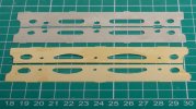
The first S23 tenders had frames with oval cut-outs, and these tenders were paired with early Y14s and with other locomotives including the T26/E4 2-4-0. Some of these tenders were released to stock when their locos were withdrawn and came to be paired with late Y14s such as 564.

Tenders built after 1893 had frames with sausage-shaped cut outs and these are represented in Big Jims’ kit for the Y14. I want to model a loco and tender from around 1890, so oval cut outs.

DSC_0907.jpg

Yesterday I went to the show at the Whitwell and Reepham Station, where I met a most helpful chap Tom who was exhibiting his layout ‘Thurstable Lane’. Tom has built the Alan Gibson 7mm kit for an E4, and explained that this kit includes both styles of tender frame. He also explained, he had the unused pair of frames sitting in his car :cool:
 

Oz7mm

Western Thunderer
Some years ago I did the artwork for the alternate tender underframes and for the tender cab and had a couple of sets produced, though not for my own use so I can't show you the result. Following this thread I am beginning to doubt how accurate they might be but IIRC they were done from official drawings.

John
 

Richard Gawler

Western Thunderer
I think I was extremely lucky, but I suppose there are spare frames out there somewhere from every completed E4. The Gibson frames are a fraction of a mm longer than the ones from Big Jim so they will file down to fit.
 
Last edited:

Richard Gawler

Western Thunderer
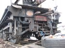
Here is a cropped pic of the genuine article that shows one of the vacant holes in the tender headstock:

I also have a copyright photo of 65420 in 1956 taken from the rear and the tender has no safety chains. The loco was steam brake only but the holes in the tender buffer beam can be determined.

I have found an excellent photo of the back of the tender of J15 no. 65445, taken at Maldon East in 1958.

This photo is in Len Wilkinson's book, "The Witham to Maldon Railway - A Pictorial History", published by Essex Transport Publishing in 2010, reprinted 2011.

This photo shows the two holes for the safety chains to be square not round, and also the clear line where the coving overhangs the sides of the tender by 1/4 inch or so.
 

Richard Gawler

Western Thunderer
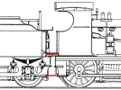
Please, do we know the approximate vertical location of the water pipe from tender to loco?

Screenshot 2022-10-25 15.20.26.png

I have extracted this drawing by Jim McGeown from his kit instructions and added the two red lines.

Possibly someone might be able to say "about a third of the way down from the top line" or whatever. My idea is, to disguise an electrical connection from model tender to model loco as the water pipe.
 
Top