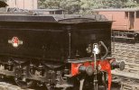
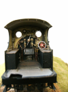
Prototype Ex-GER Y14 (LNER J15) preserved at the North Norfolk Railway

Richard Gawler

Western Thunderer
Super images Richard! But please beware of them, as the engine is not what it seems.

. . .

To anyone searching for reference, please be aware that this particular locomotive is such a glorious mish-mash that any attempt to untangle fact from fiction will inevitably lead to confusion and error!

Can you tell I am a bit passionate about it?!

Pete.

P1040366.jpg

Pete I am unashamedly quoting you here because you might just know . . . thinking about the locomotives and tenders built new in 1889 or 1890 (batches R23, T23, Y23, U25 and Y25), would the tenders have carried the safety chains during the 1890s?

I am doubtful, but then again I have simply looked at a few dozen photos of different locos and failed to spot any safety chains. They were too lowly for Lyn D Brooks to include in their near-exhaustive accounts of the locos published in the GERS Jounal in 1983.

I want to solder my model buffer beam onto the floor of my model tender, and I don't know whether to drill the holes for the chains.

I have resolved most of the details I want to include in my model but these chains are a bit of an unknown.
 
Last edited:

daifly

Western Thunderer
Richard

A photo of the tender rear of 65420 in the BRM Dec 1998 issue shows a 3-link coupling, no heating or vac pipes, and a hole in the buffer beam where the safety chain would have been fitted.

Dave
 

Richard Gawler

Western Thunderer
I suppose, I could drill the two holes. If I drill at 0.7 mm this will look more like 0.6 mm after the paint goes on, and a one-inch diameter hole sounds about right. I can pretend the tender has lost its safety chains or, if more evidence comes to light, add them.

All I need to do is get the holes in the right place (!), I might make some kind of drilling template first.
 

Eastsidepilot

Western Thunderer
Side safety chains went out with ear trumpets, Gardner states in the GER drawings file that they were fitted to tenders and all removed by the LNER, but most early photo's never seem to show the rear end of tenders so difficult to determine, certainly the holes for the mountings were there.
 

Eastsidepilot

Western Thunderer
I suppose, I could drill the two holes. If I drill at 0.7 mm this will look more like 0.6 mm after the paint goes on, and a one-inch diameter hole sounds about right. I can pretend the tender has lost its safety chains or, if more evidence comes to light, add them.

All I need to do is get the holes in the right place (!), I might make some kind of drilling template first.
Richard,
The centres of the holes are 1'-6" from the centre line of the tender and on the same centre line vertically as the buffers.
 

oldravendale

Western Thunderer
I have a few photos taken at Sheringham in 1968 which I'll happily put up if of any potential help. However, I think the preservation group had owned the loco for long enough by then to have already made some changes. I also have a copyright photo of 65420 in 1956 taken from the rear and the tender has no safety chains. The loco was steam brake only but the holes in the tender buffer beam can be determined.

Brian
 

Richard Gawler

Western Thunderer
I have a few photos taken at Sheringham in 1968 which I'll happily put up if of any potential help. However, I think the preservation group had owned the loco for long enough by then to have already made some changes. I also have a copyright photo of 65420 in 1956 taken from the rear and the tender has no safety chains. The loco was steam brake only but the holes in the tender buffer beam can be determined.

Brian this is a kind offer but I am trying to make a loco in 1890s condition. Because of this, I am starting from how the locos were built by the GER (recorded in detail by Lyn D Brooks) rather than trying to unpick the modifications made by the preservationists, BR, the LNER and indeed the GER. The photos of the preserved loco are really only useful as a general guide for me, but I'm glad I have shared them here.

I have some books and photos of locos, and I think I have enough now to start making the kit. It is helpful to me, the earlier locos had fewer features than the later ones.
 

michael mott

Western Thunderer
Hi Richard, thanks for the photos they do speak to the "dedication" of the enthusiasts of keeping the "history" of the railways alive.

Hi Richard
I too am more than glad that the NNR have this locomotive running to this day. I will watch your post with interest and good luck with the model…remember Rule No. 1, it is your railway so enjoy and build a “nice model”
Thanks for posting the photos.
Julian
Joe I agree with your sentiments, and further it is much better in my view to continue to work with these old pieces of the railway history to keep them operational rather that rusting away from the inside as static displays forever frozen in time as examples of what was "actual" the Lion being a good example of the same issues.
That said, I applaud those who work very hard to research and provide details of the original conditions of many of these locomotives as accurately as possible, given that they were workhorses often taken for granted.

Michael
 

Lyndhurstman

Western Thunderer

Scale7JB

Western Thunderer

Richard Gawler

Western Thunderer
I can see my model cab interior becoming a project in its own right, and an enjoyable one.

But I would like to change the subject to only part of the kit I am rather dreading - the tender flares.

DSC_0832.jpg

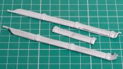
The kit provides these three castings to be soldered onto the top of the tender, to represent the flares. Please, do we have any clues about what the cast strapping here is for?

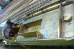
564 does not have this strapping (my third photo in this post above).

Perhaps the strapping represents brackets holding the extended coal sides, these are not fitted to 564.
 

Richard Gawler

Western Thunderer
Well, "sort of".

I have the John Gardner drawing, GERS number L46. The side elevation includes the coal guards added by the LNER from 1926 onwards. The plan view doesn't show the coal guards but does show these brackets I have called the 'strapping'. So I think, I can file them off.

The drawing also shows a clear step between the bottoms of the flares and the sides of the tender, while the flares on 564 seem to be a continuous entension of the tank sides. The notes with the drawing state "the 1/4 inch thick coping plate overlaps the tanks side plates, making a joint line around the top".

So I think, I should try to make the joint between the flares and the sides clear to see and well-defined, though I doubt I can manage a scale 1/4 inch.
 
Top