Nick Dunhill's Workbench - GNR Stirling Single

Chas Levin

Western Thunderer
Yep, I've found other references: thanks gents. I'd guess the chances of my finding an unbuilt one are less than minimal, but I'll live in hope...
 
Last edited:

Nick Dunhill

Western Thunderer
I had a little detour last week finishing this Broad Gauge loco.

53367012655_fb469d626d_b.jpg

This week I'm back on the Stirling Single, and will be now until it's completed.

I began by fitting up a Slater's SG29 motor, and testing the chassis under it's own power. Happily it went round a 6' radius curve with a little to spare. With the motor in place it seemed like a good time to install the eccentrics for the valve gear.

53366475391_39a29b103b_b.jpg

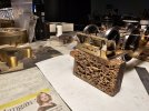
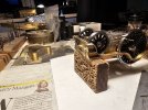
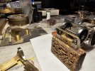
There's just enough room to squeeze a pair of eccentrics and a locating pin between the sides of the SG29 gearbox and the horn blocks. I had some steel eccentrics machined a year or two ago and cleaned 4 of them up. Soldering them directly to the axle, obviously, wasn't an option. I opened up the axle holes in the eccentrics and soldered them onto a short length of brass tube with the same ID as a Slater's axle. I drilled a 0.6 mm hole through the brass tube, up against the outer eccentric, to accept a 0.6 mm driving pin. The assemblies were held in the correct position and the axle drilled, through the holes in the brass tube, to also accept the driving pin.

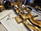
The Stephenson Link motion was assembled from Laurie Griffin castings, and will be fitted up once some cast valve rod supports arrive.

53366790919_bcb1bf3729_b.jpg

The next job was the brake gear. I had already made lots of the components, but could not assemble them until I had made the footplate, but specifically the cab steps. I had already made the footplate, see above.

It appears that the Stirling Single brake shaft trunnions are part of the cab step backing plate. Who'd have thought! I made the cab steps and then an inner assembly, attached to the chassis, to support the brake parts. This is how it is arranged

53366791074_79008ab89c_b.jpg

53366475646_9cae7bb1fc_b.jpg

53366475661_b169781cba_b.jpg

More brakes and a footplate to come soon.
 

Nick Dunhill

Western Thunderer
Lots of significant progress in the last few days. I finished fitting up the impossibly complicated brake system first. Next I made some cylinder heads in nickel-silver as the ones on the etches were in brass. I soldered them to a sheet of NS though and drilled through the half etched 'rivet' holes. I soldered fake fastners into the holes

53377997930_9601d8585a_b.jpg

As can be seen, I also added some fake fastners to the cylinder clothing at the bottom of the smokebox.

The next step was to make the front footplate, chassis sections and bufferbeam. The buffers were made self contained, and fitted within the plastikard buffer plank.

53376627302_2c7d0bcf0d_b.jpg

Lots of fake fastners were used on the front of the chassis!

53377998055_fd16f6903b_b.jpg

The wheels were placed in the chassis and the rear section of footplate fitted up such that it was perfectly level. This was done on a surface plate for accuracy. The footplate was temporarily tacked to the chassis, and the complete smokebox and front chassis soldered to it. Some brass angle was used as a strengthener, and I may add some temporary bracing before the boiler is added to stiffen the structure.

On the real loco the bogie splasher is attached to the chassis, and is releaved to fit round the cylinders. On my model the splasher is fixed to the bogie, and I cut away a small section, very similar in shape and size to the real loco, and enlarged it, bit by bit, until the loco went round a 6' rad curve!

53377904399_44095291af_b.jpg

As you can see it didn't need much grinding.

With a rolling chassis complete I thought it would be good to fit up the valve gear and check for free running. I had recieved a pair of 3D printed valve blocks from Mike Hopkins at Scale Factor (he's sent quite a lot of fittings for the build,) and these were fitted to the chassis.

53377998285_3657d7093c_b.jpg

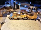
The eccentric straps were fitted to the eccentrics on either side of the gearbox. The expansion links were hung on the underslung lifting links. The inside motion worked first try, which made me very happy. I must be getting reasonably good at it!

53377550906_6c2b4be807_b.jpg

53377998325_475318c41f_b.jpg

53376627532_06f613848d_b.jpg

There's a couple of minor things to add to the chassis to complete it, then just the bodywork to complete. Not long now.....
 

Jon Nazareth

Western Thunderer
Lots of significant progress in the last few days. I finished fitting up the impossibly complicated brake system first. Next I made some cylinder heads in nickel-silver as the ones on the etches were in brass. I soldered them to a sheet of NS though and drilled through the half etched 'rivet' holes. I soldered fake fastners into the holes

View attachment 203357

As can be seen, I also added some fake fastners to the cylinder clothing at the bottom of the smokebox.

The next step was to make the front footplate, chassis sections and bufferbeam. The buffers were made self contained, and fitted within the plastikard buffer plank.

View attachment 203358

Lots of fake fastners were used on the front of the chassis!

View attachment 203359

The wheels were placed in the chassis and the rear section of footplate fitted up such that it was perfectly level. This was done on a surface plate for accuracy. The footplate was temporarily tacked to the chassis, and the complete smokebox and front chassis soldered to it. Some brass angle was used as a strengthener, and I may add some temporary bracing before the boiler is added to stiffen the structure.

On the real loco the bogie splasher is attached to the chassis, and is releaved to fit round the cylinders. On my model the splasher is fixed to the bogie, and I cut away a small section, very similar in shape and size to the real loco, and enlarged it, bit by bit, until the loco went round a 6' rad curve!

View attachment 203360

As you can see it didn't need much grinding.

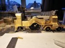
With a rolling chassis complete I thought it would be good to fit up the valve gear and check for free running. I had recieved a pair of 3D printed valve blocks from Mike Hopkins at Scale Factor (he's sent quite a lot of fittings for the build,) and these were fitted to the chassis.

View attachment 203361

The eccentric straps were fitted to the eccentrics on either side of the gearbox. The expansion links were hung on the underslung lifting links. The inside motion worked first try, which made me very happy. I must be getting reasonably good at it!

View attachment 203362

View attachment 203363

View attachment 203364

There's a couple of minor things to add to the chassis to complete it, then just the bodywork to complete. Not long now.....
Nick
I take it that your fake fasteners are brass. Where do you get them from? I used to use 16BA nuts and bolts but they have become too expensive.

Jon
 

Nick Dunhill

Western Thunderer
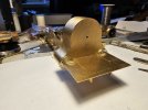
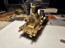
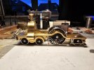
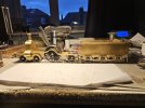
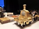
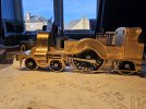
I have now made the cab and splasher assemblies. The etches were spot on and pretty easy to assemble. I took a lot of care when forming the footplate and the splashers therefore fitted without any drama or fakery. Here's everything tacked together.

53401478390_6a9a4c335b_b.jpg

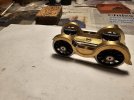
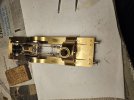
I then made the front guard irons and all the components for the slidebars, piston glands and crossheads. The slidebars are simply cut from brass section, the piston glands are made using telescoping tubing and some left-over flange etchings. The crossheads are made from scrap brass and nickel silver and some rods. You can see in this picture the way I attached them to the piston rear using drills, rods and the crossheads as spacers and jigs. All very satisfactory and not a 3D print in sight!

53401049181_1f2666c669_b.jpg

The etches for the rods came from Mick Davies and his magic CAD. Some prototypical looking crankpin nuts were also made.

53401478515_de18ac9f38_b.jpg

I also worked my way through a fairly lenghty list of other details such as vacuum pipes, assorted lubricators, a couple of long reach rods (reversing and cylinder drain cock.) I added some cast cylinder drain cocks using modified Laurie Griffin castings.

Now I just need to put on my Big-Boy's Pants and make the boiler. A lot of the above detail work was really just aversion therapy, as the boiler is going to be very tricky.

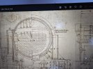
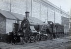
The boiler clothing on the real loco is flattened as it passes behind the back of the sand boxes and splasher. You can see it here in the drawing. Also if you look at the second boiler band in this photo of no 1008 you can clearly see that the curve flattens out ahead of the sand box.

53401484075_6484e26f6a_b.jpg

52009888182_b5a83d8f1b_b.jpg

The issues with making a boiler to fit are also exacerbated by the facts that the boiler will be prototypical diameter but the frames, and therefore splashers and sand boxes, will be closer together. I'm fully expecting to have to make a second boiler before I get something that fits nicely.

If anyone could tell me what the rivet detail looks like on the top of an atlantic cab (as pic) I'd be grateful for your help.

53401049301_f606a6cf58_b.jpg
 

simond

Western Thunderer
Nick,

your boiler looks very challenging in sheet metal. It could be machined from suitable thick wall tube (or solid bar :)) )

atb
Simon
 
Top