john lewsey
Western Thunderer
Blimey that's nice


") .
.
 .....Hut, Mantel, Reisepaß, Einzelfahrkarte........gehen


Hi Nick , i love the way you say ' and added some bolt detail ' to the self contained buffers . Did you use bits of wire in drilled holes or 3D printed heads or ????? Please explain .This week began by adding the beading that goes up the front of the tender, along the top of the flare all the way round, and down the front at the other side. Luckily the rear corners are slash cut, and not rounded, which makes the job a lot easier. The etch had some coal rails thereon that were added next. They were fixed in place using 1.4 mm rod, laid on the top of the flare, as a spacer. Half round brass was planted on the coal rail etch to match the bead round the flare.
I modified a pair of Slater's buffers to be self contained, and added bolt details. They were attached to the rear buffer beam with some guard irons cut from scrap nickel silver sheet.
A great big bag of castings and 3D prints turned up JIT. I revisited the tender chassis to finish the brake rigging and add some vac and water pipework details.
View attachment 197924
The hand brake and water valve handles were added to the tender front and the buffers on the front drag beam. Some of the lamp irons were fitted. These were the ones with lining over the cloverleaf base. The outer and upper lamp irons lie over the lining on the rear of the tender and were left off. I had a discussion with the painter first to find the best way forward to paint the rear of the tender and therefore what to make detachable to facilitate this. You can see in this picture where I have lightly scored the position of the lining and drilled holes to locate the lamp iron castings.
View attachment 197925
I fixed the tender top and division plate in place. The brief is to fill the tender with coal after paint, so I didn't bother making the coal space and then plating it over! Mick Davies 3D printed me a nice water filler to finish the tender top. He'll be making a tool box soon too!
The last job was to assemble and fit the axleboxes and springs. I had alternative brass or 3D printed parts and elected to use the cast brass springs and hangers as they were much more sturdy than the 3D printed ones. I used 3D printed axleboxes though as they needed a slight modification to the rear. It's much easier to file away resin.
View attachment 197926
Apart from the aforementioned water fillers and brake blocks all the castings came from Mike Hopkins at Scale-Factors. They are of the highest quality in brass and resin form. Mike has been developing a range of GNR parts for a while, and I lucked-out finding him at a show before I began the project. He had castings ready to go.
So here's the finished tender waiting for me to build the loco. The vacuum pipe staunchion finishes short to avoid conflict with a Kadee coupler pocket to be added post paint.
View attachment 197927
View attachment 197928
View attachment 197929
View attachment 197930
Tim Tam , why did you bother asking .Beautiful work as usual Nick, however the crucial question in the expat group remains...
Penguin or tim tam?
Ahhh , that's whats on the plate Nick . I have to say that it's really an excuse for a Lamington . It should be twice as thick for a start .Hi Paul.
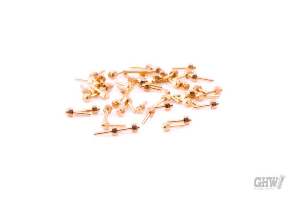
I buy fake fastners from here:
Or you can get the old Scale Hardware range from Model Motorcars Ltd in Florida.
I just drill holes in the corners of the bufferbeams and solder them in.
Easy.
I have to say that I'm not really a fan of either Penguins or Tim Tams, but I do like Lamingtons.
Hello John, do you happen to remember who did the 4mm kit please?There was a 4mm etch kit years ago
Hi Chas , I understand that it was by Steflox models.Hello John, do you happen to remember who did the 4mm kit please?
Hi Chas , I understand that it was by Steflox models.