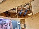
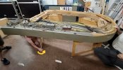
And now for something a little bit different. When CF was last being erected Justin Colson took a few pictures of the various stages involved for setting up the main ring of baseboards. I don’t think anyone has shown how layouts get assembled on RMWeb, and if they have, it is very unlikely that they are as complex as CF. Many of you will have seen all this happening at shows; please forgive me if it’s a bit boring. So here goes, with a few comments along the way.
The first part of the layout to be made was the north end and that is where setting up begins. There are four fiddle yard boards that get bolted together as a ‘C’ laying on their side. The leg boxes that these sit on can be seen in the foreground, the redlines show the baseboard joints.

This whole assembly is lifted onto the leg boxes which are set out at the correct distance using a length of string as a gauge (at Keen House there are marks on the floor.) The leg boxes also act as storage containers and have levelling feet at the bottom.

Here, Simon Humphries is demonstrating that all bolts are equal but some are more equal than others, with Rob Stewart looking on whimsically. Very occasionally a longer bolt will be needed in a particular joint - these ought to be marked - but where’s the fun in that?

The two front Holloway Bank boards are removed from their case and bolted together, whilst resting on their sides on the floor. Our 10mm bolts are a precise fit in 8” steel tubes in each board, ensuring reasonably reliable alignment and strength. The direction the bolt is inserted can be seen by the blue arrow. The second bolt is on the floor (green circle).

The whole of the HB front is then lifted onto the open gate legs and two bolts inserted at each end from underneath. At the south end the bolts both go in the same direction.

At the north end they go in opposite directions. Our next job will be to mark up bolt direction on the layout underside. Getting these bolts in place can be quite a struggle because the floor may not be level or flat.

Once the first ring is set up, the gates are taken away from supporting the layout and it is then precisely levelled, using a bespoke spirit level on known reference marks.

Once these four feet are adjusted to make the boards absolutely level, then the gate legs are moved back under the layout to give more support, taking up the level with their own feet (yellow arrow).

The next stage is to put in place the massive Belle Isle board. This travels in its own case and is quite tricky to handle. It also travels with the NLR link board which can be seen in the top left of the box. In order to lift it out of the box there is a massive truncheon-like rod which is screwed firmly into the framework (white arrow - it also has other ruder names) as well as a steel ‘bale hook’ that engages with a hole in the RH baseboard end. Two individuals then lift the board vertically in the box whilst another two move the box away from the board. It is then rested on its back face awaiting assembly.

Prior to lifting into place the three baseboard bolts and nut closers are laid out on the floor (green circles) whilst the fixing holes are show with blue arrows. For the first ten years of construction, this was more or less the full extent of the layout.

The longitudinal position of the leg box supporting this board is located by using the important piece of string with marks on it. A team of three-four people then lift this board into place, resting a lip onto the northern boards. Meanwhile, a brave soul goes underneath and slips in the long steel bolts and does up the nut closers. It is then levelled, paying attention to its level in the L & R as well as front to back directions.

It is important to check out the central baseboard joint for all alignments on the six GNR lines that cross it as well as the hidden NLR link board. Various ‘persuading’ instruments may be called in to play.

TBC
Tim
 .
.  .
.


