You are using an out of date browser. It may not display this or other websites correctly.
You should upgrade or use an alternative browser.
You should upgrade or use an alternative browser.
4mm Monks: perhaps NOT a Classic Minories - for a grandchild.
- Thread starter jonte
- Start date
jonte
Western Thunderer
Thank you, Jan, and I hope all is well with you.
I’m still a long way off attempting those ‘Swiss watch’ like chassis of yours, though, my friend
")
Jonte
Roger Pound
Western Thunderer
Nicely executed indeed, Jon, perhaps you would care to consider a diorama within the station of 4mm workmen (or should that be workpersons?  ) repairing the damaged beam..............?
Roger.
) repairing the damaged beam..............?Roger
.jonte
Western Thunderer
Many thanks for your kind words of encouragement, Simon.Jonte
great to see progress! And it's looking really rather good!
more please!
Simon
Progress has been a little slower than anticipated, although things have begun to pick up again of late.
Next, I have to contend with cutting out and fixing a couple of hundred or so paper slates, so could be several more days before there’s anything to show, but will gladly keep you apprised

Jonte
jonte
Western Thunderer
Howdy, Roger and thank you for kind endorsementNicely executed indeed, Jon, perhaps you would care to consider a diorama within the station of 4mm workmen (or should that be workpersons?
Roger
Now that seemed a great idea, my friend, until I remembered: the scene is set only weeks from a long overdue closure, so rather than repairing, they’d - more likely - be in the process of tearing it down

Still, I suppose they could also be removing - it as per the sagging architrave on the real thing - before it comes crashing down on all and sundry
Thanks for dropping by, Roger.
Jon
jonte
Western Thunderer
Hi Matt, and many thanks for the complimentHi Jonte,
This is looking excellent, especially the weathered wood!
Matt
Essentially, I’ve tried to tell a story of sorts, with exposed areas in different states of ‘distress’ (from almost virgin wood to decaying) in an effort to try and convey the tale, but still with a nod to Banbury.
As I’m always in two minds about the finish (most areas have been reworked more than once as methods used successfully before, didn’t work again, for some reason!) your compliment comes as great relief, so thank you.
Jon
jonte
Western Thunderer
I’m off the line with regard to the tiling of the roof, unfortunately however, it’s a case of another false start.
The problem started when I used up my last sheet of ‘cheap (fine)’ graph paper to line the roof, which serves as a guide:

and which I believe produces slates of an acceptable thickness in ‘OO’ gauge.
Here’s a previous attempt using same:

(Apologies to,all those who’ve seen this image many times before!).
Try as I might, none of the local supermarkets/cheapo stores had any in stock, or had simply stopped stocking it, and as I didn’t want to put it off any longer, lest I find yet another excuse to avoid the inevitable, ordering it online and awaiting delivery was a none starter. Reluctantly, off to my local Hobbycraft store to pay top price for the stuff I went, to inspect an array of offerings, or so I thought, which would afford me the best choice. But how wrong was I….yes, it was three times the price at least of what I’d usually pay as expected, but only one type was available. Fair enough, it was more Stoneyhurst/Harrow/Eaton College in quality, but therein lay the problem: I wanted the thin Ruffwood Comp. stuff (no offence to some of the fine scholars who’ve passed through those hallowed doors and continue to do so !); it was just too thick for the job. But with it being a case of ‘beggars can’t be choosers’, so began the eye straining chore of cutting umpteen graph paper slates. At least the recent clement spell made it all a little more bearable and provided some excellent lighting for the purpose, as I whiled away many an hour at the garden table:

After tens of hundreds of the things:

I decided to make a start, and what a ‘not totally unexpected’ disappointment it proved:


(Apologies for poor quality shots taken with iPhone).
Accepting defeat (why didn’t I just cut several to test!), I’ve decided to bite the bullet and remove the few I’ve laid, before spending most of today widening my search for cheapo, thin graph paper!!
Of course, all of this aggravation could have been avoided if I’d taken up @simond ’s extremely kind offer of laser printing/cutting them for me, but being the stubborn fool I am…….. Thank you once again, Simon, for yet another kind offer of help in any case
So back to ‘square’ one it is.
Jonte
The problem started when I used up my last sheet of ‘cheap (fine)’ graph paper to line the roof, which serves as a guide:
and which I believe produces slates of an acceptable thickness in ‘OO’ gauge.
Here’s a previous attempt using same:
(Apologies to,all those who’ve seen this image many times before!).
Try as I might, none of the local supermarkets/cheapo stores had any in stock, or had simply stopped stocking it, and as I didn’t want to put it off any longer, lest I find yet another excuse to avoid the inevitable, ordering it online and awaiting delivery was a none starter. Reluctantly, off to my local Hobbycraft store to pay top price for the stuff I went, to inspect an array of offerings, or so I thought, which would afford me the best choice. But how wrong was I….yes, it was three times the price at least of what I’d usually pay as expected, but only one type was available. Fair enough, it was more Stoneyhurst/Harrow/Eaton College in quality, but therein lay the problem: I wanted the thin Ruffwood Comp. stuff (no offence to some of the fine scholars who’ve passed through those hallowed doors and continue to do so !); it was just too thick for the job. But with it being a case of ‘beggars can’t be choosers’, so began the eye straining chore of cutting umpteen graph paper slates. At least the recent clement spell made it all a little more bearable and provided some excellent lighting for the purpose, as I whiled away many an hour at the garden table:
After tens of hundreds of the things:
I decided to make a start, and what a ‘not totally unexpected’ disappointment it proved:
(Apologies for poor quality shots taken with iPhone).
Accepting defeat (why didn’t I just cut several to test!), I’ve decided to bite the bullet and remove the few I’ve laid, before spending most of today widening my search for cheapo, thin graph paper!!
Of course, all of this aggravation could have been avoided if I’d taken up @simond ’s extremely kind offer of laser printing/cutting them for me, but being the stubborn fool I am…….. Thank you once again, Simon, for yet another kind offer of help in any case
So back to ‘square’ one it is.
Jonte
simond
Western Thunderer
Jonte,
sorry to hear of your tribulations…
the offer’s still open, but won’t be for a week at least as the laser needs some attention, it’s not behaving itself, and I’m away at the moment.
if you can wait that long, I’ll happily eliminate the drudgery of cutting slates, but I can’t solve the material issue.
I guess at least it doesn’t have to be squared paper. Slates are somewhat less than 1/4” thick, so I guess something of the order of 0.1mm paper would be suitable. I guess standard photocopy paper might be ok, though I’d have to measure it.
atb
Simon
jonte
Western Thunderer
Yep, something of that order, Simon, which is approximately the thickness of the previous graph paper (wash glue onto the back of it and you can see through it!).Jonte,
sorry to hear of your tribulations…
the offer’s still open, but won’t be for a week at least as the laser needs some attention, it’s not behaving itself, and I’m away at the moment.
if you can wait that long, I’ll happily eliminate the drudgery of cutting slates, but I can’t solve the material issue.
I guess at least it doesn’t have to be squared paper. Slates are somewhat less than 1/4” thick, so I guess something of the order of 0.1mm paper would be suitable. I guess standard photocopy paper might be ok, though I’d have to measure it.
atb
Simon
Wife’s just rung to say that an early outing to a supermarket outside of my immediate environs has proved fruitless, so plan b) is about to be executed!
Many thanks once again, Simon, but I’m determined to make it hard for myself
Enjoy your hols!
Jon
jonte
Western Thunderer
Hi Phil, and many thanks for your input.Someone recommended using cartridge paper for roof slates in 4mm, I got a book full and then drew up a grid by changing the size of the squares in a spreadsheet to represent a slate, I then printed it off on the cartridge paper and spent ages cutting them out.
Indeed, something of that order will be fine - of which I’ve plenty! - but the thought of marking out all those lines with a pencil (printer recently went u/s and as unlikely to need one in future it won’t be replaced)
If push comes to shove, I might still opt for this as the local library has recently reopened post pandemic, so I could always book a half hour slot and print some off for a nominal fee
Cheers, Phil.
Jon
jonte
Western Thunderer
Just a line to say that I managed to eventually locate some finer grade graph paper as required, although the spacings of 5 squared millimetres could ideally have been smaller. Thankful for small mercies, it’ll do.
So it was out with the wet and dry of various grades to remove the error of the day before, and then a case of reinstating the guide lines with a pencil:

Thankfully, having used the Pva glue quite sparingly, most of the printed lines were still visible once removed.
Then a sample was cut from the paper, and a trial run conducted to confirm suitability :

Yep. I’m much happier with that.
Many thanks once again to my fellow WT-ers who kindly offered their assistance and advice")
Jonte.
So it was out with the wet and dry of various grades to remove the error of the day before, and then a case of reinstating the guide lines with a pencil:
Thankfully, having used the Pva glue quite sparingly, most of the printed lines were still visible once removed.
Then a sample was cut from the paper, and a trial run conducted to confirm suitability :
Yep. I’m much happier with that.
Many thanks once again to my fellow WT-ers who kindly offered their assistance and advice
Jonte.
jonte
Western Thunderer
After a pleasant, but busy, day yesterday celebrating my wife’s birthday with family and friends, I popped out earlier to the railway room to collect the ‘roof’, where I’d left it out of harms way.
However, on collection, that wavy black line twixt eaves and cast iron support created by the removable, but flimsy, construct became glaringly obvious; too obvious in fact, more so than I’d first thought, so something had to be done about it!
Digging deep inside an old shoe box that harbours old odds n sods that might one day come in handy, I came across a fret of Wills’ chimney pots, barge boards and guttering amongst other auxiliary bits n pieces. Haphazardly breaking one off, I poked it into the nearest ‘gap’:

(Edit as posting picture also posted post)
Will continue on new post.
Jonte
However, on collection, that wavy black line twixt eaves and cast iron support created by the removable, but flimsy, construct became glaringly obvious; too obvious in fact, more so than I’d first thought, so something had to be done about it!
Digging deep inside an old shoe box that harbours old odds n sods that might one day come in handy, I came across a fret of Wills’ chimney pots, barge boards and guttering amongst other auxiliary bits n pieces. Haphazardly breaking one off, I poked it into the nearest ‘gap’:
(Edit as posting picture also posted post
)Will continue on new post.
Jonte
jonte
Western Thunderer
Apologies. I’ll continue.
I think it looks okay, and better than ‘the gap’, so will glue some together to an appropriate length for both sides, which I’ll secure to the cast iron beams rather than the roof, which will need removing and repainting anyway. During my search of the shoe box, I also occasioned upon a Peco downspout or two, so might even add those at the ends somehow.
I’ve also amended the title of this thread, as - I think anyway - it’s the portability of this design which makes it a classic, the hinged section firming probably the primary part. The problem I have with it (and which has been nagging me for some time) is that it’s unwieldy for two reasons: first, the weight of the baseboard section being opened/closed forces it to meander from its plane, which can place undue pressure on the hinges unless great care is taken to control it (what the long term effects of this haphazard procedure will be, heaven only knows) and two, due to the height of the bench on which it sits, the layout cannot be folded without striking the ceiling, thus I have to ask for assistance to lift to the floor before facing the first challenge!
Unfortunately, this isn’t the only issue. Followers of my thread may remember - as I originally suspected on fitting them - that the ‘bling’ catches either side, which not only draw the sections tightly together but are supposed to ensure alignment in both planes, gave up the ghost after only a couple of assemblies, requiring post assembly remedy in the form of an old baseboard connector I had lying around. Of course, this would have been easier during baseboard construction as I suggested, but my - ahum - assistant was eager to push on…… Anyway, with the assistance of a drill section add on and the layout firmly braced by a screw through the overhead bearer and a brace formed of a two by one off cut, it was eventually fitted:


However, I still wasn’t happy, as threading the bolt through the hollow dowels wasn’t as fluid as it should have been, leading to concern that the frictional force would eventually lead to the dowels becoming a loose fit (it really was a pain trying to ensure the drill hole was perfectly horizontal, despite removal of wooden bearers and electrical sections which impeded progress).
So what gives?
Well, somewhere stashed away in yet another box stored in my railway room, are several hinges that have had their pins removed and replaced by removable bits of wire of suitable diameter, and which were themselves removed from an old, unsuccessful layout. Fitted a la Barry Norman style i.e. to the sides and beneath both sides of the joint, they provided stability in both planes, and which I have to admit, never failed to do their job in the umpteen times I had assemble and disassemble it.
So, when I’ve eventually completed my roof tiling task, I’m going to take a break from model building, and address the problem once and for all.
Hence, the amended thread title.
Cheers.
Jonte
I think it looks okay, and better than ‘the gap’, so will glue some together to an appropriate length for both sides, which I’ll secure to the cast iron beams rather than the roof, which will need removing and repainting anyway. During my search of the shoe box, I also occasioned upon a Peco downspout or two, so might even add those at the ends somehow.
I’ve also amended the title of this thread, as - I think anyway - it’s the portability of this design which makes it a classic, the hinged section firming probably the primary part. The problem I have with it (and which has been nagging me for some time) is that it’s unwieldy for two reasons: first, the weight of the baseboard section being opened/closed forces it to meander from its plane, which can place undue pressure on the hinges unless great care is taken to control it (what the long term effects of this haphazard procedure will be, heaven only knows) and two, due to the height of the bench on which it sits, the layout cannot be folded without striking the ceiling, thus I have to ask for assistance to lift to the floor before facing the first challenge!
Unfortunately, this isn’t the only issue. Followers of my thread may remember - as I originally suspected on fitting them - that the ‘bling’ catches either side, which not only draw the sections tightly together but are supposed to ensure alignment in both planes, gave up the ghost after only a couple of assemblies, requiring post assembly remedy in the form of an old baseboard connector I had lying around. Of course, this would have been easier during baseboard construction as I suggested, but my - ahum - assistant was eager to push on…… Anyway, with the assistance of a drill section add on and the layout firmly braced by a screw through the overhead bearer and a brace formed of a two by one off cut, it was eventually fitted:
However, I still wasn’t happy, as threading the bolt through the hollow dowels wasn’t as fluid as it should have been, leading to concern that the frictional force would eventually lead to the dowels becoming a loose fit (it really was a pain trying to ensure the drill hole was perfectly horizontal, despite removal of wooden bearers and electrical sections which impeded progress).
So what gives?
Well, somewhere stashed away in yet another box stored in my railway room, are several hinges that have had their pins removed and replaced by removable bits of wire of suitable diameter, and which were themselves removed from an old, unsuccessful layout. Fitted a la Barry Norman style i.e. to the sides and beneath both sides of the joint, they provided stability in both planes, and which I have to admit, never failed to do their job in the umpteen times I had assemble and disassemble it.
So, when I’ve eventually completed my roof tiling task, I’m going to take a break from model building, and address the problem once and for all.
Hence, the amended thread title.
Cheers.
Jonte
jonte
Western Thunderer
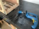
I couldn’t put it off any longer, so I addressed the failing board joining catches mentioned in my last.
Despite searching high and low, however, I couldn’t find the hinges and their bespoke pins I’d reclaimed from a previous project, so putting it down to experience, popped out to the retail park and purchased several sets of ‘hinges with removable pins’ to save me the job of grinding off the tops of standard hinges, and then mooching about for a rod of a suitable diameter to be bent to shape. I’ll probably find them next time I’m looking for something else!
On opening the packets, I discovered that one or two of the hinges displayed a tad more play than I would have liked, so selecting the cosiest, I removed each pin in turn and gave it a coating of three-in-one to aid easy removal when attached. Then I fitted one to the front side:

..and to the back:

….to prevent vertical movement (without a rebate in which to place the central pin tube, it was necessary to place slivers of card under the screw holes to keep each side as flat as possible to ease pin removal).
Then another pair of hinges were fitted underneath the boards, either end of the joint, to prevent horizontal movement towards the sides:

Also in view are four of eight ‘feet’ screwed and glued to the bases, to lift them clear of the pins. I’ll remove the screws - even though countersunk - once the glue’s dried.
Incidentally, the central board joiner - which you can just make out in that last shot - wasn’t as hard to locate as I recalled, so that will remain as belt and braces. You’ll also notice the hamfisted removal of sections of wooden bearer necessary to locate the ninety degree drill extension also mentioned in my last post.
All being well, the temporary supporting brace and top hinges can eventually be removed tomorrow and the lot disassembled to test.
Jonte
Despite searching high and low, however, I couldn’t find the hinges and their bespoke pins I’d reclaimed from a previous project, so putting it down to experience, popped out to the retail park and purchased several sets of ‘hinges with removable pins’ to save me the job of grinding off the tops of standard hinges, and then mooching about for a rod of a suitable diameter to be bent to shape. I’ll probably find them next time I’m looking for something else!
On opening the packets, I discovered that one or two of the hinges displayed a tad more play than I would have liked, so selecting the cosiest, I removed each pin in turn and gave it a coating of three-in-one to aid easy removal when attached. Then I fitted one to the front side:
..and to the back:
….to prevent vertical movement (without a rebate in which to place the central pin tube, it was necessary to place slivers of card under the screw holes to keep each side as flat as possible to ease pin removal).
Then another pair of hinges were fitted underneath the boards, either end of the joint, to prevent horizontal movement towards the sides:
Also in view are four of eight ‘feet’ screwed and glued to the bases, to lift them clear of the pins. I’ll remove the screws - even though countersunk - once the glue’s dried.
Incidentally, the central board joiner - which you can just make out in that last shot - wasn’t as hard to locate as I recalled, so that will remain as belt and braces. You’ll also notice the hamfisted removal of sections of wooden bearer necessary to locate the ninety degree drill extension also mentioned in my last post.
All being well, the temporary supporting brace and top hinges can eventually be removed tomorrow and the lot disassembled to test.
Jonte
Yorkshire Dave
Western Thunderer
I’ll probably find them next time I’m looking for something else!
That's always the way.
Ermmm, it is a test
")
jonte
Western Thunderer
Indeed, Dave: a test of my failing patienceThat's always the way.
Ermmm, it is a test. I assume there is sufficient room for the top pin to come out of the upper hinge in the photo of the underside?
( after fitting, I pushed the Hornby clerestory coach, seen in previous pictures, up and down each of the three tracks to test that the soldered joints were still true and level, only to discover that the ‘clicking’ sound it makes against the switch blade of the trailing point on the furthest track from the camera, isn’t in fact the low slung coupling after all, but the leading near side wheel. Further inspection revealed that the track section between the soldered joint and the toe end of the point, maintains its curvature when, in fact, it needs to be straight for at least a couple of inches or so leading up to an adjacent point; something I’ve discovered with this project. This was something I took great care to avoid so was a little perplexed: until I noticed that in laying, I’d wandered from the guide marks I’d made to prevent this. Further testing with other items of stock proved all was well, however, for peace of mind I’m going to relay, which means that I may have to lift the adjacent track as well if affected by overhang).As for the pin: no probs with removal, Dave, as the rear pin isn’t as close to the base as it appears, and the reason why the tiny feet I made were placed away from the ends of the boards.
Many thanks anyway for pointing this out, Dave, as I’m in the habit of overlooking things as you can see
Jonte
jonte
Western Thunderer
Well, it comes apart:


…….and stacks:

Note the ‘L’ shape pins fashioned to stop the catches flying open in use.
With the top hinges gone, I’ve inserted some dowels and drilled out some ‘receivers’ where they used to be, to prevent side shift when carrying:

I’ll fit some catches to the dowelled end to secure it totally when carried, once the glue holding the dowels in place has dried.
Then I’ll reassemble and test once the baby’s gone home, as we’ve the pleasure of having her with us today.
Btw, with regard to the coach wheel catching the switch rail which might yet lead to some relaying of track, I remembered altering the btbs on this coach last summer to counter some wheel drop. However, I only bothered doing one end as the wheels were/are a divil to get out, and as I won’t be using it, left it there. With that in mind, I carried out an earlier test and discovered that it’s the non-altered bogie wheel set that’s giving problems, which are way too narrow a distance apart. I’m much relieved as this will save a lot of messing about relaying: I’ll just have to ensure that any new stock is sporting the correct btbs (and why I’m still considering building my own locos for when I play with it). Actually, I’m already considering building the coaching stock from kits: it’s not the constructional aspect that’s bothering me about coach building (just a simple case of soldering up a rectangular box), but lining. At some point, I’m going to purchase a lining pen and give it a go.
Cheers for now.
Jonte
…….and stacks:
Note the ‘L’ shape pins fashioned to stop the catches flying open in use.
With the top hinges gone, I’ve inserted some dowels and drilled out some ‘receivers’ where they used to be, to prevent side shift when carrying:
I’ll fit some catches to the dowelled end to secure it totally when carried, once the glue holding the dowels in place has dried.
Then I’ll reassemble and test once the baby’s gone home, as we’ve the pleasure of having her with us today.
Btw, with regard to the coach wheel catching the switch rail which might yet lead to some relaying of track, I remembered altering the btbs on this coach last summer to counter some wheel drop. However, I only bothered doing one end as the wheels were/are a divil to get out, and as I won’t be using it, left it there. With that in mind, I carried out an earlier test and discovered that it’s the non-altered bogie wheel set that’s giving problems, which are way too narrow a distance apart. I’m much relieved as this will save a lot of messing about relaying: I’ll just have to ensure that any new stock is sporting the correct btbs (and why I’m still considering building my own locos for when I play with it). Actually, I’m already considering building the coaching stock from kits: it’s not the constructional aspect that’s bothering me about coach building (just a simple case of soldering up a rectangular box), but lining. At some point, I’m going to purchase a lining pen and give it a go.
Cheers for now.
Jonte