G.W.R. BLT: Almost there.

jonte

Western Thunderer
I started out with the best of intentions, collecting together a variety of parts including a piano hinge and catch to make a drop down top for ease of access, together with an offcut of aluminium to top it off, according it the air of an exhibition layout in the process.

Then I remembered my new found mission statement of ‘just get on with it’. So I did, and what followed was a complete change of tack.

An abyss size hole was cut through the surface of the board to allow a host of wires, enabling suitable control of signals, points and whatnot, to break free form the depths below, topped off with some triangular shaped offcuts (with an open back to assist in the threading through of switches in the fascia) which will serve as a panel:

8BD2F8A3-17B9-41D9-94FC-52452DBFD7DA.jpeg1D8BDBB1-C190-461C-825F-716A7E3D57F8.jpeg4D05A634-48CC-4DD3-83F8-7B14BEBA69AA.jpeg

Okay, not what was intended as outlined, but it’s done and I can now move forward to the wiring up and - hopefully - making it all work.

Cheers for now.

jonte
 

Lyndhurstman

Western Thunderer
Hello @jonte

I wholeheartedly support you Mission Statement. If you don't mind, I may appropriate it into the Rule Book for the increasingly lethargic workforce at Watkins Wharf. If it wasn't for Beryl, I have a feeling stumps would remain unstirred.

Cheers

Jan
 

jonte

Western Thunderer
Hello @jonte

I wholeheartedly support you Mission Statement. If you don't mind, I may appropriate it into the Rule Book for the increasingly lethargic workforce at Watkins Wharf. If it wasn't for Beryl, I have a feeling stumps would remain unstirred.

Cheers

Jan
:))

The offcuts (4mm?) don’t cut well with a saw, leaving gouged ends for wont of a better expression……

However, it has to be ‘thin’ for the integral thread of the switches, in order to allow the presence of a washer and nut either side of the hole (sometimes I only use the washer and a single nut if space is tight ;)).

Please pass on my regards to Beryl.

Jon
 

Roger Pound

Western Thunderer
However, it has to be ‘thin’ for the integral thread of the switches, in order to allow the presence of a washer and nut either side of the hole (sometimes I only use the washer and a single nut if space is tight ;)).
Jon,

You are not alone here my friend - I have used the same solution to get round the problem myself a number of times in the past and when the Cropsham panel is constructed no doubt it will be 'the same again' as they say. Keep up the good work, I really like the way this project is coming along :).

Roger.
 

Lyndhurstman

Western Thunderer
:))

The offcuts (4mm?) don’t cut well with a saw, leaving gouged ends for wont of a better expression……

However, it has to be ‘thin’ for the integral thread of the switches, in order to allow the presence of a washer and nut either side of the hole (sometimes I only use the washer and a single nut if space is tight ;)).

Please pass on my regards to Beryl.

Jon
Hi @jonte
I tend to use a hacksaw for thin ply; a 300mm one with high TPI. For all those important little places that are hard to reach, I ditch the frame, and wrap one end of the blade in insulation tape, and use it as a pad saw….

Cheers

Jan
 

jonte

Western Thunderer
Jon,

You are not alone here my friend - I have used the same solution to get round the problem myself a number of times in the past and when the Cropsham panel is constructed no doubt it will be 'the same again' as they say. Keep up the good work, I really like the way this project is coming along :).

Roger.
It’s reassuring to learn I’m in good company, Roger ;)

Best,

Jon
 

jonte

Western Thunderer
Hi @jonte
I tend to use a hacksaw for thin ply; a 300mm one with high TPI. For all those important little places that are hard to reach, I ditch the frame, and wrap one end of the blade in insulation tape, and use it as a pad saw….

Cheers

Jan
Thanks for the top tip, Jan. Another from the Wharf’s creator ferreted away :thumbs:

Incidentally, thinking ahead, I tried to order a replacement hacksaw blade (12” type), borrowed from my brother in law, in readiness for cutting the aluminium edging to form the cassettes. With it’s ‘extra fine’ cut and 32 teeth pi, I thought it ideal, so added it to the shopping list for collection at Toolfix or wherever. Transpired it had to be ordered but likely subjected to a delay by the Posties and their pending industrial action.

Good job I won’t need it immediately!

Thanks again, Jan

Jon
 

jonte

Western Thunderer
A little more work on the control panel.

For some reason, I’d clean forgotten about the on/on switches (for frog polarity switching) to accompany the ‘middle off’ type for switching the motors; for a second I went into a panic :eek: I’d already realised I’d forgotten to add clips to my order at Toolfix the other day, now it looked like another postal purchase was required for switches too…..and with a pending strike by our friendly posture to contend with :(…..Recalling I’d seen some switches somewhere, I spent most of the afternoon trawling; you know how it goes. Luckily I discovered a half used box of them containing three, to go with two others I’d found amongst the bits and bobs that are ‘stored’all over the place,thus I was back in business.

It’s all a little academic, as I’ll have to forgo modelling for a couple of days now, so I’ll leave you with what little was achieved today. Thanks for looking.

An attempt to tart up the offcuts that purport to being a control panel, and an opportunity to use up a little more of that bl**dy awful furniture paint:

C215EE68-2043-40C8-8D1C-B0B24C7A4215.jpeg

Prepared holes for point switching and frog polarity. The two on the extreme left are the isolation switches in each of the two headshunts, to prevent me crashing a loco into the buffers, which is inevitable ….:

54FBD65D-9AAF-4EC9-A342-A0037AF79A4F.jpeg

The feeds for the DCC and AC (for the point motors via CDU) are in pairs below.

Finally, the right hand side will feature sockets for the feeds to the adjacent fiddleyard (cassettes):

DC5F452C-7DBE-4F73-95CA-541937588893.jpeg

And that’s it :)

jonte
 

jonte

Western Thunderer
Only managed a couple of hours more since my last, but work continues on the wiring.

The switches that appear in pairs are thus: left hand side switch (centre off) for switching crossing blades; right hand side switch (on/on) for switching crossing polarity:

214D1174-67E9-48C0-8520-6315ACA2C82E.jpeg

The pair of sockets (bottom left) are for AC input (to power points via a CDU obtained from a local company quite reasonably priced); those bottom right are for the DCC input (they initially matched those of the AC, but apart from my regularly confused state that would inevitably see me placing the wrong leads in the wrong sockets, the plugs on the leads of my DCC controller already match the red and black sockets, which rather saves me a job :cool: In between the two pairs of sockets as described, will go a single socket for a 12V DC power supply, intended for my signals. To the very top will go a couple more on/off switches, this time to operate the (hopefully) bouncing semaphores.

As you can see from this next shot, things are already getting a little congested wiring-wise, considering this is only a small layout. I’ve tried keeping things as tidy and organised as possible by looming sets of wires together with some loops from offcuts of very thin wire from the odds n sods box, and labelling them by attaching some labelled masking tape:

32E3CA7E-A14E-4BBA-B448-1C959D1F8666.jpeg

The red and black sockets to the side in this shot are for the DCC feeds for the cassette fiddleyard.

Thanks for looking.

jonte
 

jonte

Western Thunderer
To help with identification of the toggle switches (points control, power, etc) on your control panel, toggle switch covers in a variety of colours can be acquired from various on-line sources.

View attachment 174065

Hi Dave, and many thanks for the heads-up :thumbs:

I recall (possibly magazine advert?) having seen these before; they seem a great idea.

However, I’ve decided on a more ‘economical’ approach using letters and numerals meant for station name boards and the likes. These were a first attempt, but as suspected, at just 3mm high, they’re way too small for my ailing eye sight :(:

411BC11B-6D0F-415E-A43B-A61A44504459.jpeg

Thankfully last night before I turned in, I had a root through some boxes in the model room and discovered a larger set of the same which will be duly primed and painted.

The numbers pertain to each set of switches for points, and the letters to the sidings (an extra letter will be created to include the loop). The intention is then to create a set of instructions of how to get ‘to’ or ‘from’ each siding E.g. ‘A’ (from fiddleyard) etc., which hold my interest for flicking switches! Instructions will also include the use of on/off switches where applicable and signal movements when fitted.

I hope that’s clear; apologies if I’ve only served to confuse further.

Thanks once again, Dave.

Jon
 

jonte

Western Thunderer
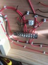
The rat’s nest of wiring has now been organised in a fashion and fixed to the underneath of the baseboard at points adjacent to the panel:

A747EDC9-55D3-4101-A0D0-C76B2E7830B9.jpeg


It should now be a simple exercise in attaching the various wires (feeds etc.) to the connections (terminal blocks and earth blocks - Bus wires), then it will be ready for testing.


jonte
 

jonte

Western Thunderer
And so it continues:

E0A526C4-D6DF-4916-A4E6-98B520353CC2.jpeg503F58A1-223F-4042-9938-BCA3EC075E27.jpeg


The locally sourced CDU was good value for less than seven quid (postage free ;)): if it fails to operate, no doubt it will be down to my ignorance. The only issue was that the presence of solder knobs on the back meant it had to be raised above the surface before being fixed down. The company provides parts for this, but I put the left over screws and collars from the Peco turnouts to good use:

0B42A7B7-22C8-4D42-8068-9C3E35799C2E.jpeg

Bit if a job trying to thread the two collars onto one small screw, so I resorted to CA-ing them together before threading onto the screw. Incidentally, I’ve always wondered how individuals manage to glue their lips together. I now how…..

I should have bought a few more of the ‘blocks’ as my wring stock is becoming seriously depleted, especially the heavier gauge for the bus. I don’t want to resort to using left over dropper wires for the job lest I incur the dreaded voltage drop.

May have see if I can source more locally as don’t want to have to break momentum or incur more postal charges.

jonte
 

Attachments

  • 95E499A2-C8FD-4209-9798-B016DB8B47EA.jpeg
    95E499A2-C8FD-4209-9798-B016DB8B47EA.jpeg
    122.1 KB · Views: 6

Yorkshire Dave

Western Thunderer
Neat :thumbs:.

Personally I'd test the circuits for continuity with a multimeter before putting power through - if you haven't already done so while going along :). It's something I always do as a matter of course since I've made layout wiring blunders in the past ;).

Though I'd be surprised at a significant voltage drop on a small layout like this.
 

simond

Western Thunderer
And cable that thick!

this link will give you a good grounding (sorry) in Voltage Drop. Thinner wire, longer wire, higher current all increase voltage drop. If you’re under 0.5V, worst case (9F with 1000 tons on) I’d not worry about it.

 
Last edited:

jonte

Western Thunderer
Neat :thumbs:.

Personally I'd test the circuits for continuity with a multimeter before putting power through - if you haven't already done so while going along :). It's something I always do as a matter of course since I've made layout wiring blunders in the past ;).

Though I'd be surprised at a significant voltage drop on a small layout like this.

And cable that thick!

this link will give you a good grounding (sorry) in Voltage Drop. Thinner wire, longer wire, higher current all increase voltage drop. If you’re under 0.5V, worst case (9F with 1000 tons on) I’d not worry about it.


Dave/Simon

What a relief! Thanks for the reassurance, both.

I can now carry on using the thinner cable of which I have enough for the Job :thumbs:

Bet wishes, gentlemen.

Jon
 

jonte

Western Thunderer
I can now report that the wiring (for the time being) is finally completed having just secured the final feed to the last point motor in the chain:

CF0A5C6F-03EE-4FDD-ADAD-09404EF29349.jpeg

As we move towards the panel end, things start to get a little busier:

288F3F4B-B670-458E-8CAC-A64F96F245A6.jpeg


At the panel end, there is now little room to breathe, all areas having been called to action (you might just make out a casualty of using a rather large drill in such proximity):

79634526-3A43-467E-A527-6D1D383FD6F4.jpeg

The additional Earth blocks to ease congestion are also in evidence.

I’m eager to test it to see if it works (or not:(), but there are still some plugs to be soldered to the AC feed, and of course, that bench needs tidying. As I’ve been feeling a little worse for wear most of the day, partly due to the effects of the increased intensity of my physio exercises to strengthen my calves from yesterday, but most likely due to the ‘jab’ (also from yesterday and which I’ve been delaying for long enough), I’m done for now.

Hopefully an early start will reveal all.

Cheers for now,

jonte
 

Allen M

Western Thunderer
Jonte and all
As well as messing with model railways I spent 50 years working in engineering electrics.
I suggest that while it is fresh in your mind you mark up on the base board or mark up a print what some, if not all of the wires do. All the info does not need to be written on just add numbers to, say , the terminal strips and make a list, It will be a big help if you need to repair or modify something in the future.

Regards
Allen
 
Last edited:

jonte

Western Thunderer
Well, it’s been a bag of mixed results in terms of electrickery I’m afraid.

The track and polarity changing switches work perfectly (although trying to recall how the DCC handset worked had me cursing once again: too lazy to dig out the booklet :oops:); that said, when everything came to a sudden halt on the middle road siding, I guessed right that I’d forgotten to connect up a feed…….. easy to lose track with all that knitting.

Unfortunately, the same can’t be said of the point motors :mad:

There’s nothing.

I’ll recheck the wiring, although all seems fine in that department (I even checked it against that of Monks). The only significant difference is between the CDUs: that of Monks - Gaugemaster - has two capacitors, whilst the one I’ve installed has only a single capacitor. Hmmm…..

If I can’t sort, I’m off to purchase another Gaugemaster, although where I’ll manage to fit it, Lord only knows!

Incidentally, I would like to convey my thanks to my good friend, Mr. Roger Pound, who kindly offered me a CDU from the kindness of his heart, plus any other bits and bobs from his Aladdin’s Cave which might be of use to me. If you’re reading this, Roger, many thanks once again, but I’m just too darned impatient ;)

I’ll leave you with one or two pics for now, and hopefully return with some better news.

Cheers for now,

jonte

3E51D6BD-F968-42B7-8D5A-4AC4CAB0B60D.jpeg2180AD48-F9E4-495B-8498-2C6A946BF04B.jpeg85506C4E-A840-40E2-BBCC-2A0EECAD8753.jpeg1B9E4FDA-FE4E-47F6-90B2-DA95B8F28528.jpeg
 
Top