Farrington Road

Dan Randall

Western Thunderer
It's not really back to front, more like a conventional one minus the rear portion. Although these may have been used as per the picture, a more likely place to find them would be in an end loading dock, obviously, with a platform or ramp behind them.


Regards

Dan
 

mfsyoung

Active Member
Is there a full-size prototype for the buffer stop installed back-to-front? Methinks that a leading bogie wheel might ride up the rail strut before the buffers reached the plank!

This is a picture taken from the 'Off the Rails' site. They are selling these as T W Ward No 11b Buffer Stop.
 

daifly

Western Thunderer
It's not really back to front, more like a conventional one minus the rear portion. Although these may have been used as per the picture, a more likely place to find them would be in an end loading dock, obviously, with a platform or ramp behind them.


Regards

Dan
Makes sense.
 

mfsyoung

Active Member
As you can see from the pictures I use brass chairs at all weak points like rail joins and soldered joints using 1mm copperclad where I cannot use the brass chairs. Check rails are soldered upright onto two copperclad strips. All copperclad strips are cut off close to the rail and half plastic chairs added.

When I am laying track using plastic chairs I always check the height using the 1mm copperclad strips. I have found in the past that sometimes the plastic softens and so the height of the rail varies, especially if a weight is added on top of the rail when setting. So I push a chair aside every so often and put a 1mm copperclad under both rails on the same sleeper with a weight on top to make sure the rail is sitting on it.
 

mfsyoung

Active Member
In my spares box I found a ten lever frame that I had intended to incorporate into one of my previous layouts so I decided that I would mechanically operate all the turnouts on this section with interlocking.

S7centralTurnoutsLabelled.png

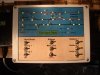
Levers 4 to 7 are mechanically connected. Lever 5 pulled locks 6 and 7. Lever 6 can only be pulled if 5 is pulled first and lever 7 can be pulled if 5 and 6 are normal. Lever 4 is not interlocked. Lever 1 controls the direction of the main line and lever 2 operates the appropriate signal depending on the setting of lever 7 (electrical interlocking) and also locks most of the other levers. Levers 3 and 8 electrically operate the crossovers on the other sections. The letters refer to the switched sections which depends on the setting of the turnouts to provide the correct track supply.

FRLeverLockingTray.jpg

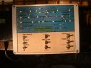
This is the locking tray which was modified from the original (I bought it second hand and it already had locking) so there are a few indents (original) which appear to do nothing.

FRLeverFrameOut.jpg

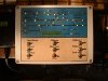
This is the output from 4 to 7 of the lever frame. 5, 6 and 7 are crossovers so one lever operates two turnouts. 1.5mm tube (0.8 internal) is threaded 14ba and a bolt with adjusting nuts is screwed in to provide the correct throw for each turnout, the excess being taken up by the slack. The required throw is nominally 2.5mm and the lever output is about 8mm. This gives plenty of adjustment for slack in the system.

FRRodding.jpg

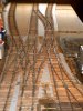
All the cranks and rodding fork ends are made from scratch and the rodding is 0.8mm hard brass rod. The rodding forks are made from 1.5mm wide nickel silver folded over 0.8mm rod and soldered. The pins are Peco blackened (about 0.5mm dia) with the heads turned down to about 0.9mm. Peco pins are also used for the pivot points of the cranks, which sit on a short tube of 1.2 mm tube (0.6mm bore) soldered to a rectangular base.

All this has taken a considerable time to construct as it was a lot of trial and error with a few disasters on the way!

Anyway, I have a great deal of satisfaction in being able to operate the turnouts mechanically instead of just flicking a switch so all the effort was worth it!
 

mfsyoung

Active Member
It is nearly two years since I last posted and unfortunately I have not been able to progress this layout due to illness. Therefore I must bow to the inevitable and offer this for sale if anyone is interested, otherwise it will just gather dust!
 

Dikitriki

Flying Squad
Hi Michael

I'm sorry you have been unable to progress this.

If you wish to offer it for sale, please can you put an ad in the members section, Small ads, and note that ad rules state that you have to show the price you are selling for.

Thanks.

Richard
 

mfsyoung

Active Member
This layout has been completed, wired and operational but needs scenery, ballast etc.
I am putting an ad in the relevant section for anyone who is interested.
 

mfsyoung

Active Member
Managed to complete the control panel which shows route setting and automatically isolates sections not set by the turnout levers.
 

Attachments

  • ControlPanel.JPG
    ControlPanel.JPG
    338.4 KB · Views: 72

mfsyoung

Active Member
This picture shows an arrival route to Platform 2 with the appropriate signal set.
 

Attachments

  • Plat2Arrival.JPG
    Plat2Arrival.JPG
    337.2 KB · Views: 70

mfsyoung

Active Member
The lights turn from green to yellow on Platform 1 showing that lever 6 has been thrown to enable shunting on the headshunt.

You can just see my loco controller on the left which is a simple but very effective voltage controller with the reverse switch located centre bottom of the panel.
 

Attachments

  • Plat1HS.JPG
    Plat1HS.JPG
    336 KB · Views: 69

mfsyoung

Active Member
Great to see you back here Michael, the panel looks good. How's the layout coming on ?

ATB Mick


Not really back, I'm afraid. I felt that I had to make the layout complete mechanically and electrically as I still intend to sell it. I have also completed the documentation (circuit diagrams) and the baseboards are also labelled underneath enabling quick fault finding if necessary!

It is a shame as I intended to finish and exhibit this layout but old age has crept up on me and realistically I would not be up to attending exhibitions. I just hope that someone comes along and is able to add scenery and rolling stock to complete and show how good S7 can look!
 

mfsyoung

Active Member
As some of you might be aware I have put my layout on ebay to see what the response is. If I sell this layout I will probably go back to P4 and dabble in that as I got the taste for tracklaying!
 

Attachments

  • Pointwork.jpg
    Pointwork.jpg
    263.4 KB · Views: 45
Top