Brettell Road, 1960s black country (ish)

Jim smith-wright

Western Thunderer
Bit of a mixed bag this post, starting with;

A kind gift.

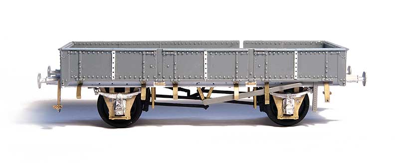
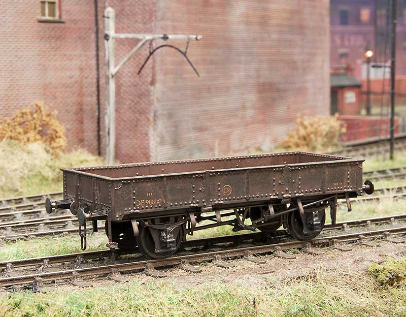
My friend Tom contacted me to say he had an old Millholme models kit for an LMS 30t bogie bolster and did I want it? Of course it would be rude not too!

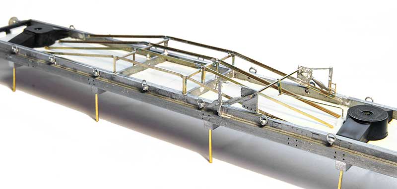
The kit represents, as best as I can tell, a diagram 1682 45 ft bogie bolster. These were a continuation of a Midland design with the only obvious difference being that the earlier ones had handbrake wheels rather than compound levers. The sides and solebars were, nicely, cast in one piece and being as old kit the bufferbeam and ends where missing. The trussing was also cast in whitemetal and was somewhat optimistic as its a long piece in a not very strong and somewhat bendy material.

LMS-bogie-bolster-underside.jpg

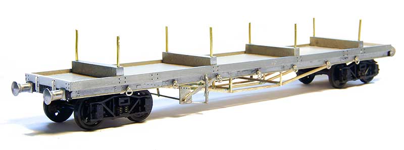
So to work I replaced all the trussing with 1mm L section brass from Eileens. The brake lever castings were OK and they are both mounted at one end. It appears that only the bogie at this end is braked at all.

LMS-bogie-bolster.jpg

The bogies are ratio ones and I ditched the swivelling plate idea as supplied preferring to pack them out and mount them with a screw. The bufferbeams were from my scrap kit parts box and the extra rivet detail from Archers transfers. The buffers were the ones supplied in the kit.
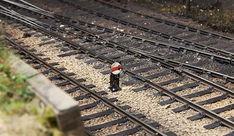
LMS-bogie-bolster-final.jpg


Lampost conundrum

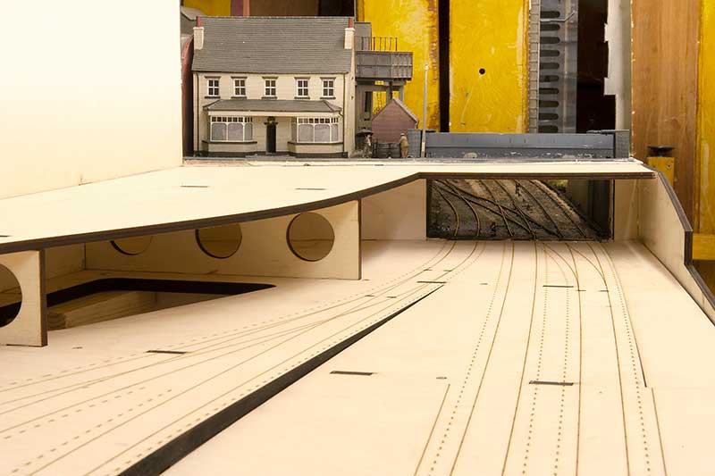
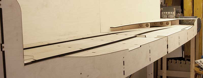
My plan to extend Brettell Road includes completing the road currently on the left of the layout as well as adding a new road. Digging around looking at local pictures in the late 50s the lamposts seem to be mostly the concrete cast type. Theres a couple of options for these. Hornby Scaledale none working ones and woodland scenics working type. I immediately discounted the latter as they are far too chunky and just look awful.

Hornby-lampost.jpg

Not that the Hornby ones look any better. Im not sure why they bothered to produce these as they are basically crude lumps of resin and they don't even provide a foot for modellers to mount them. The idea of fitting a surface mount LED and hiding the wires on the none viewing side went out of the window! I must be able to do something better than this surely? Especially as, at most I will only need 5 of them.
comcrete-lampost-raw.jpg

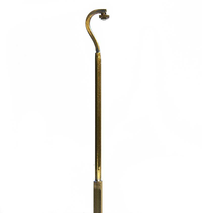
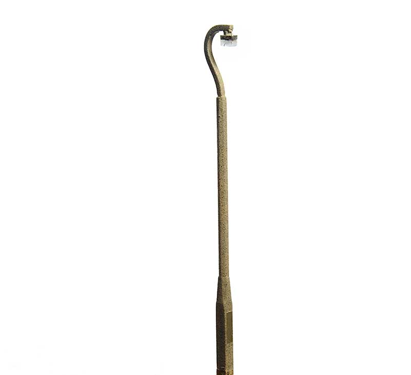
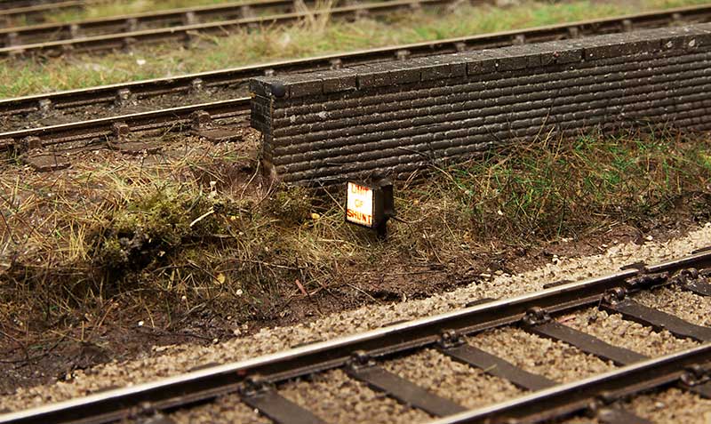
So with some K&S metal section (1.5mm square for the top and 2.4mm Hex for the main trunk) I made this.
comcrete-lampost-final.jpg

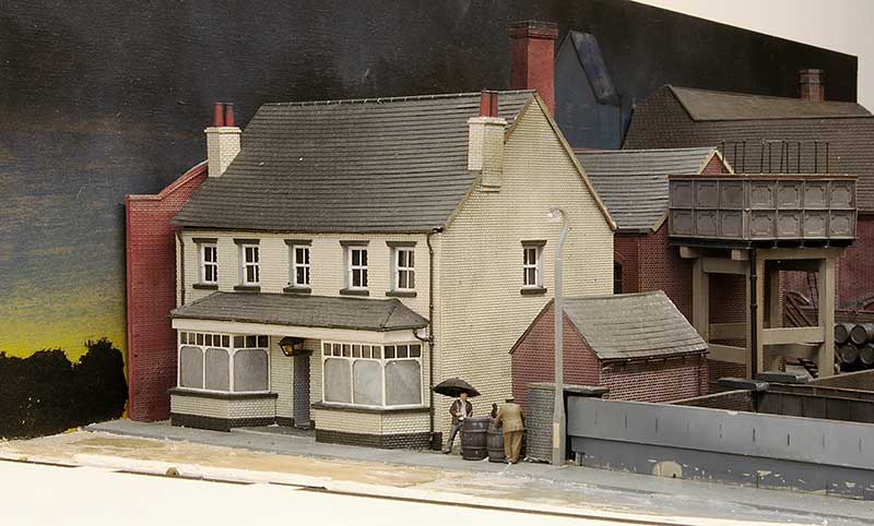
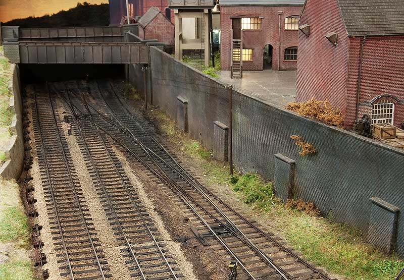
The base was blended into the main columns and sprayed with Plasticote suede. I also very lighty dusted some grey primer and blank over it to give a more concretey colouring. Below is how it looks in position.
lamppost-in-position.jpg


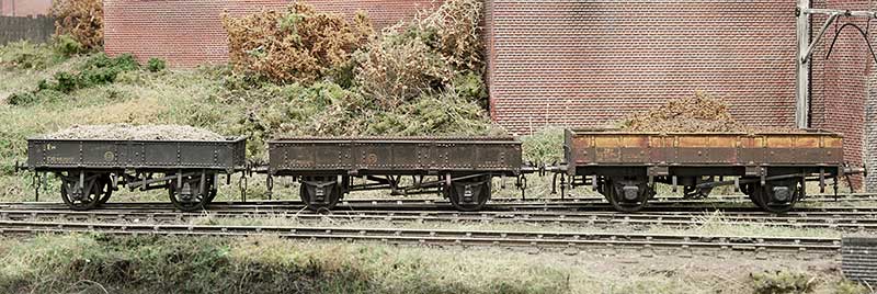
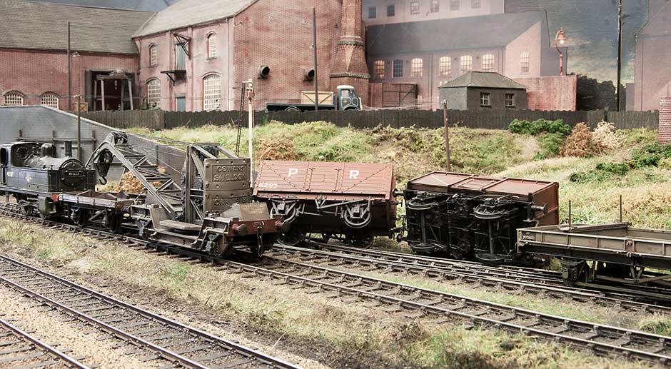
Flicking through Simon Bendall's bookazine 'Modelling British Railways - Engineers wagons' I was taken by a wagon I'd not come across before. The GWR designed ling. A 14 ton open wagon that looks like a baby grampus. In the bookazine, Hywel Thomas built one by cutting down a Chivers Tunney but I decided another route would be to stretch a Cambrian starfish instead.
GWR-Ling.jpg

So 2 starfish kits were found and a lot of cutting ensued. The doors on a Ling are shorter than a Starfish so each door had a section cut from the middle with new strapping from microstrip. Buffers are from Lanarkshire models, W irons from Bill Bedford, door bangers and steps from Rumney Models and the test of the underframe from plastic section and the spares box.
GWR-Ling-final.jpg


ballast-opens-compared.jpg

Above is the reason i referred to this wagon as a baby grampus. Along side one it's considerably smaller. Comparisons between the shortened doors and the starfish originals can also be seen.
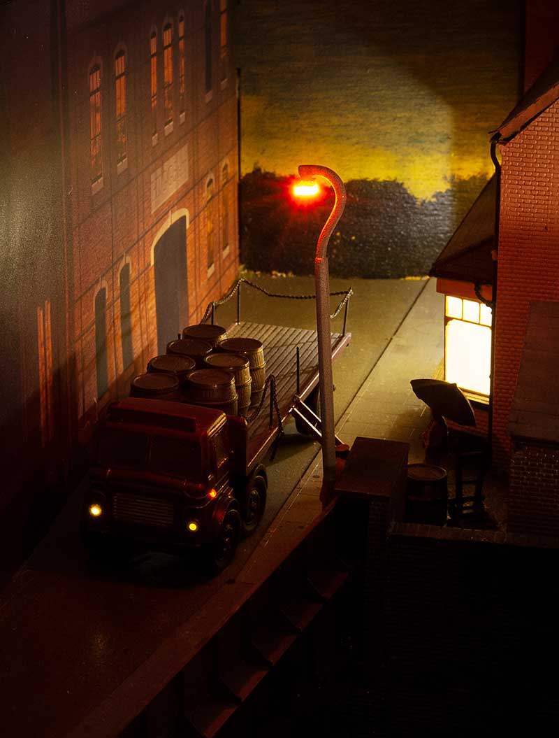
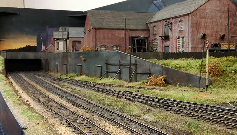
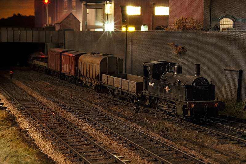
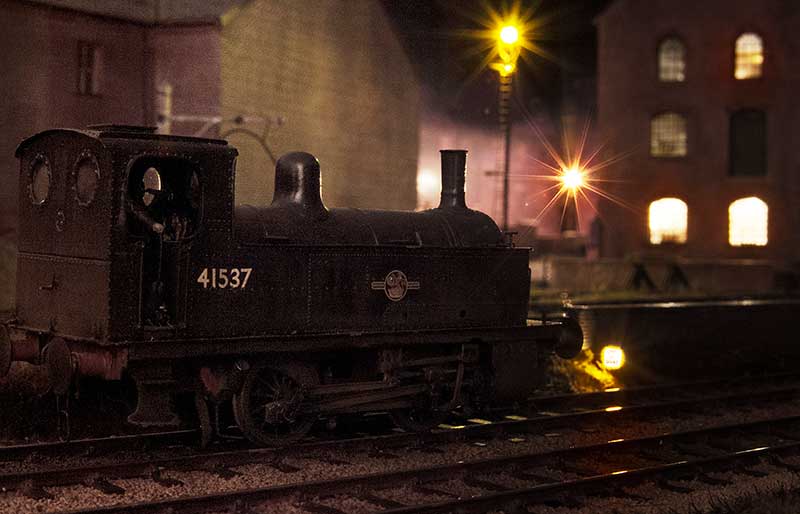
 

Jim smith-wright

Western Thunderer
It seems that the good folk of Brierley Hill need to rely on buses for a while...
brettell-road-new-track.jpg

...Brettell Road is currently somewhat disrupted! Work progressing on the plan to double track the layout. One of the advantages of designing a layout on a computer and having a friendly laser cutting chap is you can design bits to replace things you really should have thought more about the first time!

Ive talked before about the regret at not making the layout a double track and I've also touched on using MDF as a trackbed which turned out to be a tad too unstable. The main lines have been replaced with 6mm ply and a hole cut for it to sit in. Pictures of Brettell Lane in the period show some encroachment of flat bottom trackwork but in the form of pointwork. Further down the line, north of Dudley the Midland lines were also flat bottom in the period I am modelling and since Brettell road has always been more Midland anyway I decided to go with flat bottom trackwork for the plain lines. Specifically mills clips courtesy of Colin Craig. (the actual clips will be added after testing.

new-slip.jpg


Chains of slips under bridges all seem oddly familiar for some reason! Like my other model nothing in this one is straight either! The track on the left isn’t fixed at this end yet

Thanks to Colin and Tim for their assistance in supplying bits.
 

Jim smith-wright

Western Thunderer
Well the engineering works, true to form, over ran and took a bit longer than I expected. However the mini people of Brierley Hill will be pleased to hear that services can resume.
brettell-road-new-track-2.jpg

I used to be a fan of the JLTRT track colour spray paint but as that range is long gone now and my last can was pretty much done for an alternative was required. Halfords do a 'camouflage' range of very matt colours in their rattle cans and the brown is ideal as a basic track colour.
BR-new-track-through-bridge.jpg

The completed track ballasted and weathered from under the bridge. The blocks on the right are for the point rodding and I haven't fitted the point motors yet.
BR-new-track-overview.jpg

BR-new-track-LH-end-1.jpg

The left hand end from the other side of the bridge. I have a couple of ground signals to add yet.
BR-new-track-LH-end-2.jpg

BR-new-track-RH-end.jpg

And the right hand end. This is the end that required the most adjustment of whats already there.
reworked-canal-bridge.jpg

The bridges over the canal have been adapted to fit in their new locations. I still have a bit of work to bed them in properly and I intend to fit a couple of central girders between the tracks on both levels.
BR-new-bridge.jpg

The nearer buffer stop has been repositioned slightly and a new bridge built. I decided to angle it a little and do a bit of scruffy road to go behind it.
old-meets-new.jpg

Old meets new!
 

Allen M

Western Thunderer
If it wasn't for the edge of the baseboard just visible in a couple of photos I would suggest porkies and it was the real place.
It certainly captures the atmosphere as I remember when starting to work in that area in the 1960s.
Regards
Allen Morgan
 

Jim smith-wright

Western Thunderer
Part of the process in upgrading Brettell Road and preparing it for part 2 was to redo the wiring. Those that have been following from the start will recall that it was initially only a plaything and not an exhibition layout and the wiring reflected that being just 4 wired between boards. 2 for the DCC and 2 for the AC supply. A concession was made after the first show to provide short protection for each board but its not really how things should be done so its been mostly stripped out and done again.

So now the DCC is split into 3 sections. One for the yard, one for the mainlines and one for the accessories. Theres little point having short protection if said short cuts off the ability to throw the points and resolve it. The AC is also split into 2 sections as well, the second being a DC supply for LEDs. You can use AC for LEDs anyway but the flicker can be noticeable sometimes. So now theres 10 wires between boards instead.

Signals

The new arrangement for entering the yard has required a few new signals as well.
CRW_0894.jpg

Mainly a couple of ground signals from the MSE kits. I need a couple more for part 2 (one of which is a double) so I built them all together. These are powered by servos controlled by a Tam Valley control board. http://tamvalleydepot.com/products/quadservodecoder.html
limit-of-shunt-signal.jpg

I guess this also comes under signals? A simple limit of shunt sign from a MSE lamp a bit of brass tube and some microstrip.

Below a couple of mood shots.
deeley-shunting-1.jpg

deeley-shunt-limit.jpg

shunting.jpg
 

Jim smith-wright

Western Thunderer
BR-oops.jpg


Behind the scenes I have migrated my site to a new hosting company. All has gone pretty well but there was an oops! I did lose was the subscribers list, unfortunately. So with apologies can I ask all those who wish to still receive updates re-subscribe to my site? Its dead simple. Go to www.p4newstreet.com click on any of the workbenches and on the right you can pop in your email where it says follow. Remember to click the confirmation link in the email you are sent and thats it. Again apologies for the inconvenience and if you spot anything else thats broken feel free to drop me an email.
 
Last edited:

Jim smith-wright

Western Thunderer
rebuild-complete.jpg

With the point rodding redone and signal wires back in place theres not really anything left to do on Brettell Road part 1. I was hoping to embrace the latest technology with the rodding and decided to go with 3d printed BR stools from Modelu. However those didn't work out for me at all and proved to be far too fragile. Ive sent them all back and Alan is going to investigate as he believes there was a problem with the resin. I'll do a follow up post when he comes back with his findings. So as the old adage goes, sometimes its best to stick with what you know I went back to the trusty Brassmasters etched ones instead.

point-rodding.jpg

The cranks are also Brassmasters although I've used the MSE bases as I thought they were better. The rodding itself and signal posts are also from MSE with the signal wires from ezline. Unlike the previous version where I made some of the point rodding work, just to see if i could, I didn't feel any need to to it again.

detectors.jpg

A few more detectors for the ground signals were knocked up from bits of brass and my rain technique of coats of Tamiya smoke and AK wet effects fluid reapplied. I guess you could say I'm back to where I was a few months ago!

just-a-peek.jpg

Theres something oh so familiar about glimpses of grubby track between bridges and retaining walls.

bridges-done.jpg

At the other end of the layout the extra bits of the bridges have been added.

AK-gravel-amd-sand-fixer.jpg

One thing I forgot to mention before is this stuff. Its great for fixing ballast and while its no where near as cheap as the traditional PVA/ water/ washing up liquid concoction it can be used straight from the bottle with no messing around wetting everything first.
 

Jordan

Mid-Western Thunderer
While I very much like and admire the new track, what I like even more is the sunset backscene at the left hand end!
Yes the sky scene adds something. Very nice.
:eek: Sunset??!!?? :confused: That's the glow from the furnaces at Round Oak steelworks!!! :rolleyes: :p :D

The double track makes a lot of sense, especially when it is taken into account that the nearby 'Bumble Hole' Line from Old Hill to Dudley was always just a quiet branch really, but even so was double track all the way.
 

Jim smith-wright

Western Thunderer
The Black Country was once described as black by day and red by night. It’s also rumoured it inspired Tolkien in his creation of Mordor. In the railways world, at least for enthusiasts, Mordor was a common nickname for New Street.
 

PaxtonP4

Western Thunderer
More than just a rumor. The shire is Warwickshire particularly Moseley wood. The twin towers are the Birmingham University tower and the waterworks tower at Edgbaston and yes the Black Country is Mordor.
 
Last edited:

Jim smith-wright

Western Thunderer
I guess I was supposed to be here about a year ago but Covid happened. I actually had a trip over to Tims planned between the first and second lock down but that got delayed to the start of this week. Tim Kindly agreed to me using his laser cutters for 3 days but in the event it only took 2 to do the new boards for Brettell Road. I must say there was only a few of the most minor amendments needed which I was very pleased about and unlike some of our previous efforts next to no scrap bits this time!

old-layout-meets-new.jpg

Here we see the new board meeting the old. Perhaps one of the biggest advantages of drawing baseboards up digitally and cutting them on a machine is that everything should be consistent. In the event the track bed was about a mill and half too high which considering I had rebuilt the main lines wasn't to bad at all. Nothing a few minutes with a saw and a chisel didn't fix anyway! The end back scene from the original layout has been cut away.

BR2-new-boards.jpg

Overview of the 2 new boards. Unlike the previous boards the mainline is flat on these boards with the yard rising behind them. Kings Heath station was the inspiration for this arrangement. Time will tell if I need to get creative about how the wagons in the yard stay put.

BR2-towards-stourbridge.jpg

Looking towards Stourbridge. The platforms will fill all of the view here along the mainlines I have a thing for stations with much longer platforms than the trains that serve them. I wonder if its because much of the norther half of the North Warwickshire Line had stations like this (as a kid our garden backed onto it)?

unseen-pub-side.jpg

With hindsight it was probably a good thing i was a tad obsessive about the buildings and detailed up the side of the pub that, at the time of building it, I never thought anyone would see!
 

Dave Holt

Western Thunderer
Very impressive, Jim.
Looking at the track alignment under the bridge, in the first photo, the two outer tracks appear to sweep round to meet the existing track very nicely, but the middle track looks to meet with a bit of a sharp kink or is that just a photographic illusion?
The late Ray Hammond used to fit a small pad of foam rubber bearing on top of the fixed axle to prevent the shuttling sometimes seen with stock having AJ couplings and pin-point bearings. That might be enough to prevent unwanted movement on the inclined sidings.
And, yes, what a bonus that you fully detailed the, originally, hidden side of the pub. Some parts of my Holt/Delph layout are decidedly Hollywood film set - no cosmetic chairs on the non-viewing side, for instance.
Enjoying watching your progress.
Dave.
 
Top