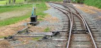
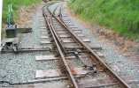
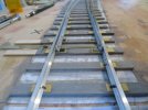
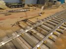
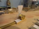
A small country halt somewhere west of Middlesex

AJC

Western Thunderer
I am curious about this arrangement.View attachment 178523 I am guessing this is another of your pictures Martin
Does one of the levers connect electrically to signalling, because all the linkages appear to operate from one initial rod.

Michael

Not sure what signalling Castell Caereinion has now, but that’s the usual Welshpool and Llanfair arrangement - the frame is unlocked (see the box at the base of the blue lever) by Annett’s key in order to and the frame operable. My understanding is a bit hazy, but the key is attached to the single line staff and all the line’s loops and sidings were like that. There isn’t (or wasn’t, last time I went) any fixed signalling or track circuits there.

Adam
 
Last edited:

AJC

Western Thunderer
Thanks Adam, do you know what the box that is linked to the bar at the very tip of the blades is for?

michael

Just the mechanical point lock, operated from the blue, locking, lever. Despite the ‘box there, the loop is basically a double ended siding, locked at each end, independently.

Adam
 

michael mott

Western Thunderer
Thanks again for your info Adam, going back to the Templot link and revisiting all the pictures I spotted the second rod from the frame so now it all makes sense.

Michael
 
  • Like
Reactions: AJC

martin_wynne

Western Thunderer
@michael mott

Hi Michael,

There are in fact 2 rods, as can be seen clearly in this more recent Google Streetview: Google Maps

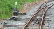
Also it is possible to see both rods in this view:

castle_caereinion_levers1.jpg

The black lever moves the points. The blue lever operates the Facing Points Lock, which unusually is located on an extended timber and linked by rod to the lock stretcher bar, rather than located directly between the rails. A Facing Points Lock is legally required for passenger movements over facing points.

There is no actual signalling, the blue lever is released by a key on the single line token carried on the locomotive. The box on the side of the lever is the lock. You can see a close-up of the levers and lock in this link:

Castle Caereinion | Signalling Photos

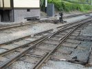
At the other end of the loop the Facing Points Lock is arranged more conventionally acting directly on the lock stretcher bar:

castle_caereinion_levers3.jpg

castle_caereinion_levers2.jpg

This is Castle Caereinion station on the 2ft-6in narrow gauge Welshpool and Llanfair Light Railway in mid-Wales, UK.

My pictures were taken in 2002, so more than 20 years ago now. Where does the time go? There are likely to have been some changes since then, as you can see in the Google Streetview.

cheers,

Martin.
 

Phil O

Western Thunderer
To give a little more detail, the key, either an Annetts or one attached to the token, is inserted in the box attached to the blue lever, which allows the blue locking lever to be pulled, releasing the lock in the switch stretcher, allowing the black turnout lever be pulled.
 

cbrailways

Western Thunderer
There is some mechanical interlocking within the frame that prevents Lever 2 being reversed before Lever 1 is reversed. if you didn't have that then it would be possible to attempt to reverse Lever 2 before Lever 1 is fully reversed. When Lever 1 is reversed the Annetts Key or Key Token is held captive in the lock on Lever 1 also through the mechanical locking.
 

simond

Western Thunderer
Well, it’s like cricket.

you have to put the key in, and then you can pull a lever out, and when that levers out you can pull the other lever out but you have to then put the first lever back in, or the second lever might go in by accident, and you don’t want that because it might cause an accident.

when the train’s gone by, you can pull the first lever out, put the second lever in, put the first lever back in and take the key out.

clear now?
 

michael mott

Western Thunderer
Reading the last two posts, had me laughing out loud, sometimes one just has to see the funny side of life. Especially since I have really been struggling with getting the blades to not only look decent but actually function decently as well.
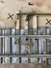
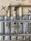
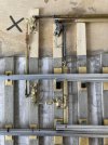
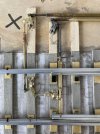
Given that there are what seems to be endless varieties of switch stretchers and locking mechanisms, I have simplified things just to get it working properly, using a single bar under the blades like this one which I believe is one of Martins pictures
104-0462_IMG - Copyx1024.jpg

Notice that there is no lock at the tip of the blades, but I will be putting one on, I just have not decided which type yet.
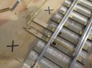
first the cleaned up tips of the blades, I did need to make a new straight blade.
IMG_5462x1024.jpg

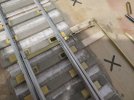
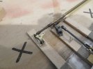
The new linkage to the ground frame is started. the large 0x80 flat head screw is just a placeholder while i figure out the support bracketsall the other screws are 00x90 the one connecting the bar is a commercial one all the rest I made on the lathe.

IMG_5468x1024.jpg

IMG_5469x1024.jpg

The wagon rolls nicely over the points now without derailing. So I feel that i am making some progress.

Michael
 

76043

Western Thunderer
Michael, as it stands your turnout without a lock would be for a siding away from the running line and with protection from a trap point closer to said running line, likely as per the picture. I believe a mechanical point lock always has a second set of levers, which you say you will be adding in due course, but non-working?

I've been struggling with the same understanding of facing point locks etc, so these pics are really helpful. Thanks!

These docs from the IRSE have been really useful.

Lovely modelling.
Tony
 
Last edited:

cbrailways

Western Thunderer
Sorry chaps (and chapesses), I didn't mean for it to be complicated. Essentially, the workings just don't apply to the physical equipment connected to the switch rails (yes, they are known as switch rails and not blades) but also apply to the mechanical interlocking that is hidden away at the rear of the ground frame levers. The mechanical interlocking is like a mechanical computer in that its arrangement is in a form of logic controller that prevents an operator from causing an incorrect and potentially unsafe sequence of events from occuring (i.e. a derailment or collision).

A Facing Point Lock (FPL) is, in the UK at least, a legal requirement that all facing points used by passenger traffic are held in position by a mechanism independent of the actual point throw mechanisim. It is simply a bolt that passes into and out of notches cut into a bar (yes) that is connected between both switch rails. On a 'big railway' its usually, but not always, done in the 4ft, but on narrow gauge railways, as space there is restricted, it can be done to one side as in the photographs above.

Still very good modelling ;)
 
Last edited:

Northroader

Western Thunderer
You can find FPL operation combined with point operation in a single lever, as an economical measure. The ones on the Lynton and Barnstaple are examples of this.
 

michael mott

Western Thunderer
These docs from the IRSE have been really useful.
Lovely modelling.
Thank you Tony that was an interesting read. I will be making the lock a working one, this is a small layout and more for the pleasure of creating a bit of rural railway scenery that is fictitious but believable, also as a cameo for photographs. I will be happy if I can accomplish that, and by doing this I am learning a great deal as well.
Plus it keeps me off the streets and out of trouble.:)

Sorry chaps (and chapesses), I didn't mean for it to be complicated.
No worries Chris, and thanks for the heads up on the nomenclature. "Switch rails" makes sense.

The ones on the Lynton and Barnstaple are examples of this.
Do you have a picture ?

Michael
 

chigley

Western Thunderer
Well, it’s like cricket.

you have to put the key in, and then you can pull a lever out, and when that levers out you can pull the other lever out but you have to then put the first lever back in, or the second lever might go in by accident, and you don’t want that because it might cause an accident.

when the train’s gone by, you can pull the first lever out, put the second lever in, put the first lever back in and take the key out.

clear now?
Ithought it changed the frog polarity :D nice work michael

Ken
 

michael mott

Western Thunderer
It only took a week or so but I now have a locking set of switch rails.
1 locked on the main road

IMG_1083x1024.jpg

2 unlocked

IMG_1084x1024.jpg

3 rails moved to the loop

IMG_1085x1024.jpg

4 rails locked on the loop

IMG_1086x1024.jpg

Well that took a bit of back ache and colorful words but now I know how to do it. So some cosmetic work now to tidy it all up. and then build the ground frame.

Michael
 

michael mott

Western Thunderer
I have started the lever frame and doing a bit of mock up work.
IMG_5486x1014.jpg

IMG_5485x1024.jpg

Everything is just balanced, and I see I will need to make the control bars much smaller in section to look even reasonable, the printed levers are 48 inches long and the chequer plate is supposed to be 1/48 scale but it looks way to big for that. the timbers are approx 6x6 the three rods are a scale 1 inch in diameter. I think that everything is going to need scaling down a bunch.

IMG_5486x1014.jpg
 
Top