john lewsey
Western Thunderer
Excellent Kevin, just Excellent.
Your engine looks really nice.A real Lady.
Your engine looks really nice.A real Lady.

Oh, it's a real PROBLEM!Excellent Kevin, just Excellent.
Your engine looks really nice.A real Lady.

Sorry about that - but video are huge space hogs so just can't accomodate. Better to use a video hosting site, ie youtube or vimeo etc and we'll happily post links to the video.I'd post a video, but WT does not facilitate that.

A report on MY Problem Class: I had determined to power the tender. I put two motors and gearboxes in it. A massive failure: they fought each other and destroyed the decoder, drat! After a bit of work, I now have one motor driving the front axle, rigid in the frames, the middle axle floating, and the rear axle rocking. I had to abandon picking up from the middle axle, as the wheels would not turn. It seems to pull well; my rake of five six wheelers is all disassemble and in the paint shop, languishing.


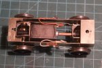


Dave, you anticipated me. I had bought two MSC 25:1 gearboxes, to hang on two axles each with a motor. A dismal failure. Today I (in two attempts) made up a "cannon" bearing. It has a spigot the size of the opening in the gearbox, with a 2mm bore down the length, and sticking out where the motor would be, is a 6mm dia bearing about 10mm long. When mounted on an axle and wheels, it looks like a cannon. I admit I own a lathe. I'll post a pic or two tomorrow. Thanks to John in his forbearance of me hijacking his thread, but most of the notes on my build would just be duplicates of John's, and I don't see much point in a new thread.Hi Kevin, Another solution is to create a drive similar to an A-1-A using SDMP/Finney 7 power and remote gearboxes primarily designed for diesels and electrics. Templates can be downloaded to aid planning. SDMP Gearbox and Drive Components for 7mm Scale Model Locomotive Kits
View attachment 267482
I also built one for a battery loco which has a shorter wheelbase.
View attachment 267485
This photo shows how it appears from the side when fitted - the motor is just visible.
View attachment 267486
@john lewsey - apologies for the brief thread hijack.
Dave, I sent you a PM.Hi Kevin, Another solution is to create a drive similar to an A-1-A using SDMP/Finney 7 power and remote gearboxes primarily designed for diesels and electrics. Templates can be downloaded to aid planning. SDMP Gearbox and Drive Components for 7mm Scale Model Locomotive Kits
I created a 10' Bo-Bo drive using their Power which attaches to the motor (right) and Remote (left) gearboxes. The issue you may have depending upon whether you are prepared to compromise is the ensemble sits fairly low and may be visible.
View attachment 267484
View attachment 267482
I also built one for a battery loco which has a shorter wheelbase.
View attachment 267485
This photo shows how it appears from the side when fitted - the motor is just visible.
View attachment 267486
@john lewsey - apologies for the brief thread hijack.

It also might be worth loosening each worm gear and/or UJ joint in turn to see if the issue can be narrowed down to one axle. Although in isolation each maybe fine but working together it may cause the problem.You could try a different motor but other solutions, such as incorporating thrust bearings on the shaft, aren't so easy.
Dave, I sent you a PM.
My first suspicion would be the axial thrust load of the worms, which reverses direction between forwards and backwards running. It also increases with load on the motor so the problem only appears when moving the tender body. I'm not familiar with the motor but it may not be designed for axial loads in both directions, or it could be the UJ locking up. You could try a different motor but other solutions, such as incorporating thrust bearings on the shaft, aren't so easy.
ABC Gears tender drive units include a spur gear from the motor shaft to a lay shaft that runs between the two axles, and uses helical gears on the final drive - which reduce but don't eliminate the axial thrust. That arrangement does ensure that the axial thrust isn't transmitted to the motor.
Sorry, but I don't have an easy cure.
LGB put a ball bearing either end of the motor shaft to stop their twin ended motor shafts from moving out of mesh.
It also might be worth loosening each worm gear and/or UJ joint in turn to see if the issue can be narrowed down to one axle. Although in isolation each maybe fine but working together it may cause the problem.


I don't mind, it's all interestingI initially found this type of drive can be tricky to set up and after experimentation I use non-traditional railway modelling solutions, albeit for shorter wheelbases.
One is to use neoprene tube and a ball bearing to create a CV joint (this drive bogie is in my 7mm Met Bo-Bo).
View attachment 267878
And in a shorter wheelbase I halved the shafts by grinding a flat on the ends (this drive is on 1/8'' axles and fully compensated using Alan Gibson 4mm hornblocks in a 7mm scale BEL battery loco - fundamentally a wagon chassis).
View attachment 267877
In both cases a torque/torsion bar was fitted linking the two gearboxes to minimise fore and aft rocking and lateral twisting. In the wagon chassis I also used a copper tube sleeve to keep the drive line in a straight line.
View attachment 267879
Both of these drives work for the applications I use them for.
Once again @john lewsey - apologies for cluttering your thread.
Nick, thanks for the thoughts. I ASSUME the motor has thrust bearings. The universal is hard against the cannon bearing on the right, so that acts as a thrust bearing, and the worm on the right is also against the cannon bearing.Kevin,
My first suspicion would be the axial thrust load of the worms, which reverses direction between forwards and backwards running. It also increases with load on the motor so the problem only appears when moving the tender body. I'm not familiar with the motor but it may not be designed for axial loads in both directions, or it could be the UJ locking up. You could try a different motor but other solutions, such as incorporating thrust bearings on the shaft, aren't so easy.
ABC Gears tender drive units include a spur gear from the motor shaft to a lay shaft that runs between the two axles, and uses helical gears on the final drive - which reduce but don't eliminate the axial thrust. That arrangement does ensure that the axial thrust isn't transmitted to the motor.
Sorry, but I don't have an easy cure.
Nick
I'm not sure I don't want lateral twisting; I want the four wheels all on the track at the same time, for current collection and traction. I could still have a torsion bar between them. I could fit a tube to one of the gearboxes, with a wire soldered to the other. This would fight pitching while allowing twisting. I'll have a think about that.I initially found this type of drive can be tricky to set up and after experimentation I use non-traditional railway modelling solutions, albeit for shorter wheelbases.
One is to use neoprene tube and a ball bearing to create a CV joint (this drive bogie is in my 7mm Met Bo-Bo).
View attachment 267878
And in a shorter wheelbase I halved the shafts by grinding a flat on the ends (this drive is on 1/8'' axles and fully compensated using Alan Gibson 4mm hornblocks in a 7mm scale BEL battery loco - fundamentally a wagon chassis).
View attachment 267877
In both cases a torque/torsion bar was fitted linking the two gearboxes to minimise fore and aft rocking and lateral twisting. In the wagon chassis I also used a copper tube sleeve to keep the drive line in a straight line.
View attachment 267879
Both of these drives work for the applications I use them for.
Once again @john lewsey - apologies for cluttering your thread.
Thanks. As I write, I don't see the point of another thread, and comparing the virtues of the two drive systems on a single wheeler might be illuminating.I don't mind, it's all interesting
Sure. Although the bearing on the motor and the cannon are about .240"; I can't imagine they are offering much friction.Might it be something as simple as putting a washer between the motor and the worm at one end and the motor and UJ at the other?
![IMG_1356[2].JPG](/data/attachments/267/267400-2f2cf573971ae8554f353c162df7656f.jpg)