Ian_C's workbench - P4 and S7 allsorts

A distraction - lathe and DRO
  • Ian_C

    Western Thunderer
    Sort of a second level subroutine - using machine tools to make parts for another machine tool to (eventually) make parts for a model locomotive. But it's all designing and making things so thoroughly enjoyable. New lathe arrived and I'd set my mind on fitting DRO to it. If you're a machine tool traditionalist this lathe, a Proxxon PD400, is heretical stuff. If has a die cast aluminium headstock for a start (hrrumph....splutter...etc). For the work I intend to do it suits just fine, and unlike most of the 'hobby engineering' lathes these days it's manufactured in Europe and not China and it is very nicely made and put together. It's a relatively small lathe though, so fitting DRO on the bed, and particularly on the cross slide, was a design challenge. For those wot's interested I used compact 5 micron magnetic scales and reader heads from Machine DRO (Machine DRO | Digital Readouts | Engineering | Machinery). Hope you can make some sense of the scrap book below.
    PD 400 compilation.jpg
    All set up on the bench now. Had a test run and it all works very well. Sooner or later the old lathe and the mill/drill head will be up for sale. Anybody wanting a first lathe?
     
    The missing drop link
  • Ian_C

    Western Thunderer
    Not done much for a few weeks so it's therapeutic to get back to some modelling over the Xmas break. Thought I'd tackle one of the 'bogey jobs' . Not a set of weight relieving and guidance wheels, but one of those difficult jobs that you put off doing until inspiration strikes or you have no choice. This is the making of a crosshead drop link, a brass cast part that was missing from the kit. Sure I didn't lose it and it looks very much as if it didn't cast on the sprue, small feeder and possibly blocked by debris during casting. Either way, with no spares forthcoming making one from scratch was necessary.

    For a long time I couldn't work out how I'd make one. It's quite a complicated shape, requires a degree of precision and I couldn't see myself filing it out of a solid lump. The eventual method and notes below...
    drop link storyboard 2.jpg

    1 & 2 - I find it helps to model problem parts on CAD. Gives you a good understanding of the part and the key dimensions and often suggests possible methods of manufacture. There's enough information in the Wild Swan book on the motion drawing on page 54 to construct the part. When you break it down to basic geometry it's not as bad as it first looks.

    3 - It looked like a possible way of making the part was to mill a brass section corresponding to the end view cross section. A length of 1/2" brass bar was big enough to make the section. Flat milled on top of bar in the vice, turned over and dropped onto parallels and flat milled parallel on opposite side. The reason for using round bar and not making the initial flats too big is that the bar can be rotated in the vice to mill the angled faces of the section. It's a whole bunch easier than angling the milling head over and re-setting it afterwards.
    milling sketch.jpg
    The sketch shows how the basic section is cut from the round bar. Most of the bar is held in the vice, either on parallels between jaws or in the locating groove in the sliding jaw. The milling is done on the overhanging section. Mill the top flat (section 1) and mill the vertical datum face (on the left). Mill out sections 2 and 3. Turn it over and mill off section 4 to give the required overall thickness of the part. Mill section 5. Then hold the bar in the jaws using the remaining cylindrical faces and rotate it to the angle required to mill the angled sections 6 and 7. Easy enough except for the small angled section 7. That's just over 1mm in width and sits between two other faces. I had a go with a 1mm milling cutter, and in spite of running at maximum spindle speed and feeding ever so slowly I managed to break it before the job was done, so that face was finished with a needle file after it was removed from the mill. Finish the milling by taking the other vertical face back to give the correct overall height to the section.

    4 - There's the basic section before cutting the angled faces. Hope it all makes sense.

    5 - With the work back horizontal the end is milled square and used as a datum for drilling holes. The three bolt holes for fixing to the cross head are 0.5 mm diameter and the union link pin hole is 0.8mm diameter. I made the section long enough to drill two hole patterns on the basis that I'd either mess one up, or lose one, or if not, then I could choose the best of the two.

    6 - Turned to vertical to drill the holes for the oil reservoir bungs.

    7 - The milled and drilled blanks are removed from the bar and cleaned up. At this point you get the feeling it might just work.

    8 - Blanks again, showing the cross section.

    9 - Marking out, piercing saw and about an hour of patient filing to make the finished part. Seen from the front - the kit casting is on the left, finished part in the middle, marked blank on the right. First time lucky and didn't need the spare blank!

    10 - Seen from the rear.

    That's the drop link job crossed off the difficult list.
    ----------------------------
    Anyway - I hope all you WT types had a good xmas and I wish you a peaceful and productive 2018.
     
    "Obtain a running chassis" - part 1
  • Ian_C

    Western Thunderer
    It’s been mentioned before on WT that sometime around now the MOK instructions simply say “…obtain a running chassis…”. I suppose if you take on a kit like this it’s not unreasonable to assume that you have the gumption to turn the thing into a working chassis. Still, it’s epically terse, and I’m sure there will be plenty of challenges to overcome before I obtain a running chassis.

    I got this far before with the original Slaters wheels before deciding that they required improvement. As previously posted the Slaters wheels were converted to take home made telescopic axles. That worked out OK and the ‘Slaters shimmy’ has gone away. It’s worth noting that on the rear axle that carries the motor and gearbox the taper pin that holds the axles together has to be offset from the centre. I knew this but I hadn’t fully worked out the detail when I designed and made the axles, but as luck (I know, planning is better than luck) would have it there is just room to pin axle number 4 to one side of the gearbox. Just. One of the gearbox axle bearings had to be shortened slightly to make enough space. It’s a bit of a compromise but not tragic. The motor and gears are from ABC Gears - MINI-7E with a Maxon 352988 motor with a 30.2:1 reduction. Works well and fits in the chassis and firebox without any modification. I've had a go at some video and I'll try and work out how to post/link to it for those wot's interested.

    normal split axle.jpg
    split axle and gearbox.jpg

    There’s another problem that becomes apparent on closer inspection. The compensation doesn’t really work. The eight wheels are longitudinally compensated as four groups of two. All four compensation pivots are fixed to a chassis side plate. This produces the kinematic equivalent of a rigid four wheeled chassis. On an uneven surface one pair of compensated wheels won’t be carrying any load. That’s not quite true since the bearings on axle ends of the unloaded wheels are able to drop in the horn guides until the wheels touch the track. They only carry their own self weight though, not a good recipe for track holding.

    I had originally thought about building the chassis with CSB (continuous spring beam) suspension. Not wanting to complicate matters and wanting to press on I elected to go with the chassis as designed. Forum comments from other builders suggested that there was enough free play in the compensation to make it workable in practice. Now I have the chassis on wheels finally I can see that doesn’t work well. Adding cross chassis compensation to one pair of beams would work but would require major chassis surgery and would add parts in visible areas of the chassis. CSB likewise would require a lot of chassis re-work. The best solution I could come up with was to add spring assistance to one pair of beams. In normal running the loco sits on the compensation beams and they control loco attitude and correct ride height. When one beam becomes unloaded the springs press the unloaded axleboxes down so that the wheels contact the track and take a proportion of the nominal axle weight.

    Unsoldering the compensation beam pivots and extracting the beams is a faff and requires cutting and bending away part of an axle box guide. The beams are unsoldered and the laminated etches are separated. The inner etched beam is modified to allow a phosphor bronze wire spring to be fitted alongside the unmodified beam. The spring ends bear on the tops of the axle boxes. The compensation beams are now single thickness but still plenty strong enough to support the loco.

    There’s the question how springy the spring needs to be since I don’t yet know what the finished weight of the loco will be. I piled all the current components onto the kitchen scales and estimated how much else was to be added and came to the conclusion that the loco would weight between 1.0 kg and 1.2 kg when complete. I have spring calculations in a spread sheet, I know the length of the spring, I know the weight each spring should support and I have a choice of 0.5mm or 0.9mm phosphor bronze wire. End result is that 0.9mm PB wire set to about 1.5mm below the compensation beam level will deflect to support about 75% of the axle load when the loco is on level track with the beam ends in contact with the top of the axleboxes. It's approximate but it seems to work OK on the test track.

    Pictures being worth a thousand words and all...
    comp beam mod 1.jpg
    comp beam and spring 1.jpg
    comp beam installed 1.jpg

    ... and I will drop the unhygienic chassis back in the ultrasonic tank at some point to remove all the filing and fettling debris.
     
    "Obtain a running chassis" - part 2
  • Ian_C

    Western Thunderer
    Fitting the coupling rods for the first time was something that I was both looking forward to and not looking forward to. If successful then it's a big step towards a running chassis. If not, then something's gone wrong and it's backtracking and problem fixing. In my 4mm experience it's usually the start of a struggle with quartering and rod centres. Surprisingly the rods dropped on and it all worked first time. I shouldn't be surprised really, a lot of careful work went into chassis, rod and wheel sets, so why wouldn't it work?
    rods fitted 1.jpg
    The chassis trundled up and down a gently inclined test track with only an intermittent stiff spot. Some close examination showed the stiff spot to be caused by the inside end of the crankpins occasionally contacting the heads of the 16BA screws holding the axle box keepers to the chassis with the wheels at one extreme of side play.
    P2080002.JPG
    Thinking back, the crank bosses were reduced in thickness (see an earlier post), which left the original S7 Group crankpins threads slightly longer than the thickness of the boss. The crankpins were taken out and had a couple of threads filed off the inside ends before reinstallation. That cured the problem but the screw heads were still closer than you'd like. The eventual solution to this problem wasn't what I had imagined and will be covered in the next episode.
     
    "Obtain a running chassis" - part 3 - springtime
  • Ian_C

    Western Thunderer
    Thinking some more about the axle box keeps. The instructions suggest soldering small nuts inside the chassis and fixing the keeps with small screws. There are half etched recesses in the chassis side plates for the nuts. They are very small and the only nuts that fit are teeny weeny 16BA nuts (Eileen's Emporium - there are none in the kit). This is how it works out...
    keeps plan A.jpg
    ...and as I found in the previous episode the screw heads are a nuisance in the limited space between wheel and chassis. I figured a better solution was to put the keeps on the inside of the chassis plate, solder 14 BA nuts to the the keeps and fit them with 14BA screws. Voila...
    keeps plan B.jpg
    Although the 14BA screw heads are fatter than 16BA screw heads moving the keep inboard means that the screw heads don't project as far. And a bonus is that 14BA is slightly less of a fiddle than 16BA.

    Well, that would have been that, except I remembered about the cosmetic spring castings and wondered how they would fit around all this. Turns out that with the spring castings fitted to the chassis you cannot remove the axle boxes. I couldn't see a practical way of making the spring castings removable. After sleeping on it I decided that the axle boxes probably didn't need to come out again (painting? I may regret this, but press on) and I may as well just tack solder the keeps in place and dispense with the nuts and screws.

    The spring castings are of brass and quite nicely done. They do need to be modified to get the spring hangers to clear the compensation beams. This is shown in the instructions. You need to remove fully half of the hanger bracket and put a decent chamfer on the end to clear the compensation beam in it's extreme position. Make sure you do 4 of each hand!
    springs prepared.jpg
    Another challenge becomes apparent now. The spring hangers are to be soldered to the inside of the chassis plate. The castings have small round spigots on the hangers, presumably to locate them on the chassis. Firstly, we've just filed most of the spigot off one end, and secondly there aren't any holes etched in the chassis anyway. I'm guessing they were just missed off the etch. Locating and soldering the springs 'freestyle' inside the chassis would be an absolute a**e of a job. So we must have at least one of the locations holes in the chassis for each spring. Measure, sketch, arithmetic and marking out to locate the holes.
    spring hole.jpg

    I drilled the holes a little small and opened them up to a tight fit on the casting spigot. They pretty much stay in the right place as you tack one end, adjust and tack the other then solder both ends. There's a little spigot and solder to tidy up on the outside of the chassis. Easy enough in the end.
    spring fitted.jpg Eventually they are all fitted and the chassis starts to look a bit more like the real thing. We have snowdrops, no daffodils yet, but it's definitely springtime here.
    all springs fitted.jpg
    Next task is to refit the wheels, rods and the motor and gearbox and see how it runs under power driving from the rear axle.
     

    Attachments

    • springs prepared.jpg
      springs prepared.jpg
      214.9 KB · Views: 4
    "Obtain a running chassis" - part 1b - side play
  • Ian_C

    Western Thunderer
    Kinda forgot to mention this - axle side play and negotiating curves. Back tracking a little then.

    Plotting a 6ft radius curve on CAD and superimposing the axle centres suggested that if the side play on the front and rear axles was zero then axles 2 and 3 would need about 0.9mm side play either side to negotiate the curve. Side play on the front axle needs to be as little as possible to maintain clearance between the back of the cross head and slide bars and the coupling rod and leading crankpin. Side play on the rear axle should be minimal in order to keep the loco aligned with the (straight) track. Axles 2 and 3 can float laterally and find their own positions on straight or curved track.

    0.5 mm spacer washers were made to fit between the inside of the front wheels and the face of the axle boxes. 0.6 mm spacers were required on the rear axle. You’d think that front and rear spacers would be the same wouldn’t you? Maybe there are some small errors or accumulated tolerances in the chassis. I’m not going to worry about it. With that done, and with the help of a straight edge, I found that axles 2 and 3 had about 1.0 mm side play each way.

    One thing to note; there’s quite bit of side play between the axle boxes and the axle box guides in the chassis. That means you can’t completely eliminate side play on axles 1 and 4. Hopefully axle 1 is well enough controlled to clear the crosshead- we’ll see shortly. Altogether that arrangement should work on a 6 ft radius curve with a bit to spare.
     
    "Obtain a running chassis" - part 4 - coupling rods and under power
  • Ian_C

    Western Thunderer
    The chassis was stripped and all the parts cleaned in the ultrasonic tank to remove flux, filings and general bench debris. Back together and lightly oiled. Ran just as smoothly with the motor driving as it did freewheeling. That's a relief.

    I'd considered a number of methods for motor mounting. However you do it you want to constraint the motor from fore/aft movement but allow it to move from side to side to accommodate the rear axle sway on uneven track. There are three motor restraint brackets in the kit, one of which fitted the Maxon motor nicely. I arranged the bracket to engage the plastic end cap of the motor to reduce noise from vibration of the motor against the mount. As I had offset the motor and gearbox slightly to make room for the axle taper pin I had to elongate the bracket mounting holes a little to centre the bracket on the motor. There's also a small relief cut out to keep the wires clear of etch edges. Also worth noting that the motor restraint bracket on the chassis has been cut away to provide clearance to footplate and firebox casting but hasn't had any reinforcement added. There has been a bit of debate on one of the MOK 8F threads about whether it needs reinforcing when the side ribs are cut off like this. It doesn't. The unreinforced etch is plenty stiff enough to resist the motor reaction torque. motor restraint 1.jpg

    Here's some video of the chassis with coupling rods fitted running under power.

    It is very smooth and very quiet, which is a good thing when I come to add the DCC sound. Can't decide whether there's any benefit to be had from adding a flywheel, there's a bit of room in the firebox for one. The big shiny lump on top of the chassis is a tiny toolmaker's vice just to add enough weight to compress the springs added to the front compensation beams. There are no pick ups as the plan is to pick up from the tender (which means that I can happily kick that challenge down the road for a bit longer). The motor leads are croc clipped to wires from the controller. You can see them dragging along behind and trying to snag every obstacle on the bench. . The pony truck is just going along for the ride held down by gravity; maybe there'll be a spring when I get round to thinking about it. I'll add that the tractive effort is astonishing, an order of magnitude more than my 4mm expectations.

    Sorry about the glaring, flickering background and some ghosts where the clips fade in and out. Still trying to get my head around iMovie and this video thing. It's not as easy as I thought!
     
    Last edited:
    "Obtain a running chassis" - part 5 - cylinders, motion bracket and connecting rods
  • Ian_C

    Western Thunderer
    Some more assembling of parts made earlier and some more clearance challenges.

    While trial fitting the cylinders to the chassis the purpose of a couple of mystery parts on the etch was discovered. The etch actually had them labelled as cylinder spacers but I hadn't come across them in the instructions so had left them off pending enlightenment. They fit directly to the rear face of the cylinder sub assemblies and fill the gap between the chassis side plate and the cylinders. The value of that became obvious when fitted the cylinders to the chassis with screws for the first time. Without the spacer the chassis and cylinder backs bend when you attempt to tighten the screw. The spacer fills the gap and allows the screws be tightened properly.

    With cylinder assembly and motion bracket assembly fitted to the chassis they lined up very well and the ends of the slide bars needed only a very small adjustment to contact the pads on the motion bracket. I have noticed on the prototype that there are sometimes packing shims between slide bar ends and motion bracket. MOK 1 - Crewe 0. The drop link can be soldered to the cross head. The slide bars can then be soldered to the motion bracket. Note that when cylinders and motion bracket are joined this way the cross head becomes captive, the cross head nut not being able to pass behind the motion bracket, and if the connecting rod is permanently attached to the cross head then that also becomes part of the assembly. Make sure all the work on these parts is complete and that cross heads slide easily before joining cylinders to motion bracket.
    cyl brkt rod assy 1.jpg
    cyl brkt rod assy 2.jpg

    Anticipating a struggle for clearance behind the cross head I made sure the connecting rod..errr..connection did not project beyond the back of the cross head. The inside end of the rod was filed down a little to reduce the thickness and a small washer was turned up to go over the connecting pin cast into the back of the cross head and soldered on. The pin was filed down flush with the back of the cross head. On my cross head castings the rear flange that engages the inside edge of the slide bars was already quite thin so there was no opportunity to thin it further in pursuit of clearance. We're looking for every small bit of clearance we can gain, so worth looking to see if you can scrape a bit off the back if you're working in S7.
    cross head back 1.jpg


    With the assemblies complete they can be fitted back on the chassis and the connecting rods put on the driving crankpins. More clearance problems, but not where I'd expected them. There was a sliver of daylight between the leading crankpin nut and the back of the cross head with the leading axle over at maximum side play. Same on both sides and somewhat of a relief. Reminder - to get this result in S7 you need:
    • minimum sideplay on leading axle, there'll always be some but as little as you can engineer
    • reduce the projection of the driving wheel bosses to scale thickness, Slaters wheels being fatter than scale in this respect (earlier post)
    • counterbore the leading coupling rod and recess the leading crankpin nut, you'll need to be more or less flush with the face of the rod (earlier post)
    Thank you to those who have posted useful observations on these issues on previous MOK 8F threads. You helped me to get it right first time! Good old WT eh?

    The real clearance issue was between connecting rod and the coupling rod joint between axles 1 and 2. It turns out that the side play I'd provided on axles 2 and 3 allows the connecting rod to move across enough to strike the coupling rod joint nut.
    rod clearance 1.jpg

    Having run the chassis in a little prior to this with just the coupling rods fitted I thought I'd accurately measure the axle side play I actually ended up with as opposed to what I'd calculated I'd end up with (earlier post). Turned out that I had more side play on all axles than I'd aimed for, and that presented the opportunity to reduce the side play on axles 2 and 3 slightly. Back to the CAD drawing board and taking advantage of the actual side play on axles 1 and 4 (that I'd assumed to be zero for the purposes of constructing the geometry originally) I found that I could put spacers behind the wheels on axles 2 and 3. For what it's worth I ended up with 0.16mm spacers on axle 2 and 0.44mm spacers on axle 3. Taken together that still gives enough accommodation to negotiate a 6 ft CL radius curve with a tiny bit to spare (in theory anyway - yet to be proven!), and just gave some clearance behind the connecting rod to miss the coupling rod joint. A benefit of having a lathe is that it's the work of a few minutes to turn up spacers of any size you require, and yes it is possible to part off spacers 0.16mm thick.

    And here's Mr Stanier's 0-8-0. Look's like I'm getting somewhere.
    con rods assembled 1.jpg
    One observation, at maximum piston stroke the end of the cross head just leaves the parallel portion of the slide bars adjacent to the motion bracket. The motion drawing on page 54 of the wild Swan book shows that the prototype does a bit of this too!
     
    Last edited:
    "Obtain a running chassis" - interlude - rolling road
  • Ian_C

    Western Thunderer
    Obtaining the running chassis by driving it up and down on 3 ft of track wears thin after a while. A rolling road's what I need. So I bought a relatively low rent version from http://www.directtrainspares-burnley.co.uk . It was for O gauge 32mm and predictably S7 wasn't going to sit neatly on the rollers. Easy enough to modify though.

    The holes in the black plastic base plates were slotted out to allow the angle sections to be moved further apart. The ball bearings are a 'value' type and there's a bit of free play on the outer race. That's not a big problem in itself except the bearing inner races are bolted directly to the inside faces of the angle sections. That allows the outer race to rub against the angle under typical running conditions. 0.5mm spacers were turned to space the bearing off the angle (could probably have used M3 flat washers if I'd had any). The distance between the angles required to set the bearings at 33mm was calculated and two slots were milled in a strip of Tufnol. The rollers at one end are bolted to the Tufnol, the other sets are free to slide along the slots. The sliding rollers seem to find their own position under the wheels when running and seem happy to stay there without the need for bolts or clamps.

    rolling road 1.jpg

    Set up the loco on the rollers, applied power and off it went. But all wasn't well. Even after preventing the bearing outer race from rubbing on the angle sections there was still enough rolling resistance from the 16 bearings to cause the loco to want to climb up the rollers. It reached a perilous equilibrium, occasionally making little lunges for freedom over the leading rollers. Adding some weight to the chassis to make it sit down on the rollers caused the motor to run slower and you could hear that the drivetrain was working quite hard. The bearings were a type with a metal shield secured in the outer race. The wobbliness of the outer races caused the shield to rub on the inner races on most of the bearings. the remedy was to pry out the 32 shields with a small screwdriver. That freed things up considerably and the loco then settled down to run happily.

    rolling road with chassis 1.jpg

    In the end it's a simple device and I could probably have come up with a better solution myself for less. Knowing what I now know I'd have spent more money on a better quality of bearing. Anyway it works.

    One observation. The rolling road doesn't half amplify the wobbles. Where it seems to glide smoothly up and down the track it shuffles and shimmys on the rollers. Not totally unlike an 8F overdue for shopping trying to run at pace. Pity the Modelu crew.
     
    “Obtain a running chassis” - part 6 - return crank and eccentric rod revisited
  • Ian_C

    Western Thunderer
    A few posts ago I thought myself very clever having made a ball bearing big end for the eccentric rod. It was secured to the return crank with a small nut on the inside of the crank. A WT’er with more experience and sense than me pointed out that with a limited clearance between the crank arm and the connecting rod it was unlikely to work. That prediction came true! Back to the drawing board to rethink that one. In the end a small amount of cheating was required. Effectively I’ve turned the assembly back to front and used the bearing cover as the securing nut. I also took the opportunity to improve the appearance of the crank arm by representing the four counterbored holes present on the prototype. A picture should make the arrangement clear.

    assy explode 2.JPG

    assy explode 1.JPG
    Today we have naming of parts…

    1 - The bearing cover unsoldered from the original assembly.
    2 - A turned flange and bush. Threaded 12 BA internally and soldered to the bearing cover.
    3 - The eccentric rod.
    4 - A 12 BA stud soldered into the crank arm.
    5 - The outer layer of the crank arm.
    6 - The inner layer of the crank arm.
    7 - Another turned thingumabob. Soldered to the inside face of the crank arm and with a 10 BA stud to screw into the driving crankpin.

    Not shown - four short lengths of wire to represent the prototype studs and nuts. Soldered into the holes in the inner layer of the crank arm.

    The crank arm layers are made from 0.5mm NS sheet. Drilling holes tidily in thin sheet metal can be a challenge so the 0.5mm strip was soldered to a 0.8mm strip of scrap NS to make the job easier. The whole was screwed to an offcut of timber and clamped to the milling machine bed.
    drilling crank holes.JPG

    All the holes in the crank layers were co-ordinate drilled and the blanks cut out and unsoldered from the backing strip. A small tool was turned to help with the marking out of the crank profile. It’s just a rod with a diameter and spigot each end. The diameter of each end matches the diameter at one end of the crank.
    crank 2.jpg

    The spigot is located in the appropriate hole and the rod is scribed around. Something I’ve learned - a thin coating of solder holds the scribed lines much better than marking blue or a spirit marker pen, particularly when there’s a lot of filing and handling involved.
    marking out crank.jpg

    The parts soldered together and ready for assembly. Well, the bearing cover hasn't been soldered to the flanged nut thingy yet. The hole in the eccentric rod big end was opened out to be a clearance for the threaded bush.
    crank and rod parts.jpg

    The finished assembly.
    crank and rod assy.jpg

    The crank arm is flush on the back and clears the connecting rod, and the bearing cover/nut is easy to remove to dismantle the motion. The cheat is that the bearing cover rotates with the crank arm now rather than being fixed to the eccentric rod. In practice this isn’t very noticeable when the loco is in motion. That gets me on the way to assembling the rest of the valve gear.
     
    “Obtain a running chassis” - part 7 - valve gear pins
  • Ian_C

    Western Thunderer
    A lot of the smaller motion pins on the prototype were secured with collar and a taper pin. They're small features on the model but it's worth trying to reproduce them. A distinct improvement over seeing BA nuts or screw heads holding the valve gear together. There are a number of small motion pins that are very similar in size so I've standardised on a 0.9mm pin for all of them. Start by turning some collars, in this case 1.4mm diameter, 0.5mm thick with a 0.9mm hole through. You need to be spot on with the parting off tool on items this small, but once set up it's dead easy to knock off a handful. You'll lose a few so make some spares!

    Solder the collars to short lengths of 0.9mm wire. Put the pins in your Proxxon or Dremel mini drill and take the end of the pin nearly back to just proud of the collar with a file. Polish up what's left with an abrasive block, like Garryflex, while still in the drill.
    valve gear pins.jpg

    Fit the motion together with the pins. Cut off and dress flush on the rear of the joint. Secure with a tiny flash of solder. If the hair shirt of authenticity really itches you could try and drill through the collar 0.3mm and fit a length of wire to represent the taper pin. That's Monday evening's quota of gumption all used up.
     
    "Obtain a rolling chassis" - part 8 - valve gear complete
  • Ian_C

    Western Thunderer
    It took a lot a assembly, disassembly, adjusting and tweaking to get all the clearances right and all the parts moving without restriction, but finally the valve gear is complete on one side. I originally said I'd set the gear in neutral but decided I'd prefer to see some valve motion so I set the radius rod at about half forward gear in the expansion link. I set the gear at full forward cut off on the other side, just for the hell of it!

    Clearances were tight again, no surprises there. Getting the connecting rods to pass behind the lower part of the expansion link required some fettling. I had to file off part of the overlay on the inside face of the expansion link assembly to create clearance. If I'd known I would have just snipped off a bit of the overlay before soldering it on. Just make sure you do one of each hand!
    expansion link 1.jpg expansion link 2.jpg

    The combination lever is straight as assembled from the etched parts. If you leave it straight then there will be very little or no clearance behind the lever to the leading edge of the crosshead and it will tend to pull the front end of the union link out of line. The motion drawing on pg 54 of the Wild Swan book (easily the most referred to page in the book so far on this build, and, in the absence of detail instructions, invaluable) shows that it is slightly cranked at both ends on the prototype to bring the lower end out in line with the union link, and that provides just enough clearance for the cross head. Easy enough to do on the model part. There's an oil reservoir at the lower end of the combination lever that is not represented on the model. It isn't do-able on a flat etched part so I can understand why it's not there. I agonised for a few days and decided not to try and add it.

    The rotation of the combination lever in the valve crosshead casting needs careful attention. With the parts as supplied there's simply not enough room for the combination lever to rotate. The further you set the gear from the neutral position the more rotation you'll need at that pivot. It's relatively straightforward to open out the casting with a needle file or piercing saw.

    On the prototype the radius rod is free to slide in the expansion link, it's position in the link determined by the position of the reverser lifting lever. On the model the rod is pinned to a position on the expansion link. Kinematically then it it will conflict with the fixed position of the lifting lever when the motion is...umm...in motion. Only a little, but we want the valve gear to move freely so better to avoid the clash. Therefore I didn't pin the lifting lever through the slot in the rear end of the radius rod. I added a dummy pivot pin end to the lever and left the rear of the radius rod free between the plates of the lever. The rod appears to slide back and forth in the lever and the compromise isn't detectable.

    One last problem to overcome was the lack of restraint of the valve crosshead in its carrier. The radius rod is very light and it only takes a small amount of friction at the rod to expansion link pivot to cause the radius rod to lift on part of the stroke, and in so doing it tends to lift the combination lever a little. It doesn't stop the gear from working but you see a little hiccup in the motion when it happens and that spoils the illusion. The solution to that was to solder on a restraining bracket made from a tiny length of brass angle filed to the right height. It's added to the inside of the carrier, behind the combination lever and radius rod, so hopefully not noticeable in the murk beneath the footplate. A photo should make that clear.
    piston valve crosshead 1.jpg

    Eventually, working valve gear!
    valve gear 1.jpg
    combi lever and crosshead 1.jpg

    And, naturally, there's video...
     
    Last edited:
    Brakes - loco brake cylinder
  • Ian_C

    Western Thunderer
    Having overcome the challenges associated with making it go, attention turns to making it stop, cosmetically at least. First up, the locomotive brake cylinder. A rather ugly little white metal casting is provided. You'll not see much of it tucked away between the frames beneath the cab, but in the MOK kit it provides the anchor for the tender drawbar and the instructions direct you to drill and tap the casting 6 BA to accept the drawbar screw. There's a hole etched in a drag box plate to locate the casting (I assume) but no corresponding spigot on the top of the casting.

    Up early for F1, clocks changed, sunny morning, feels like spring might actually happen, and I'm in the mood, so a couple of hours in the workshop produced a replacement brake cylinder complete with the nuts that hold the lid on. The dimensions were scaled from one of the drawings in the Wild Swan book. Seven nuts though, so had to get the calculator out for that!

    brake cyl 1.jpg
    brake cyl 2.jpg

    brake cyl 3.jpg
     
    LMS tender plates and histories
  • Ian_C

    Western Thunderer
    Here's a diversion. I'm trying to work out what plates the tender would have carried. The Wild Swan book says that 8142 was built with a 4,000 gallon Mk2 welded tender, number 9869. It still had a Mk2 welded tender when photographed in 1965. Goodness only knows if it's the same tender, there were lots of them and they got changed around often enough. But the chances of finding a clear photo of the rear of 48142's tender in its later life are about nil, so I'm just going to assume that it was still dragging around faithful 9869. So far so good, but now it gets more difficult. Here are some questions I can't answer...

    • The loco had a build date of Feb 1942, but what build date did tender 9869 have? Could have been 1942, but not impossible for the tender to have been built at the end of 1941. I can't find any information relating LMS tender numbers to build dates.
    • There seem to have been two variants of the LMS tender number plate that was fixed the the rear of the tender. Both the same size and shape and both carry the same information: LMS, number, year of manufacture. But one type has LMS in non-serif characters, the other in rather antique looking serif characters. They're all mixed up in terms of dates. There are early LMS tenders with non-serif and late LMS tenders with the serif characters. Was it determined by custom and practice at the works where they were built? So far I've not been able to work that out.
    • Likewise there are two versions of the water capacity plate. An elliptical one (rather similar in size and shape to the typical LMS works plate on locos), and a rectangular one. Again I can't work out the reason behind tenders having one type or the other.
    • All of the tenders have two plates on the back, number plate at the top and water capacity plate at the bottom. But some tenders also had a third plate that carried LMS, place of manufacture, year of manufacture. Elliptical in shape and similar to loco works plates. Again it seems random and I can't establish any pattern to which tenders had the maker's plate and which did not. Works specific again?
    If anybody in WT land can answer the questions or point me in a useful direction then I'd be grateful.

    The reason this has my attention is that I've decided to have a go at producing some artwork for photo etching. Something I've been meaning to do for years. Seemed like a set of plates for loco and tender would be an easy way to start. I'm planning to do for the loco:
    • smokebox door plate
    • works plate
    • shed plate
    ...and for the tender...
    • number plate
    • water capacity plate
    • water shut off valve plates x2
    • water scoop in/out plate
    Initial artwork after a day's research and a few assumptions looks like this...
    etch artwork 1.jpg

    Needless to say I'll get a lot of these on a single sheet of 0.25mm brass. I'm thinking I'll fill the sheet with a load of other 8F sets using info from the Wild Swan book. If you have any requests then do let me know - although I'm not promising any timeline and there's no guarantee that my first go at etching will produce useable results!
     
    Completing the chassis - part 1 - Gubbins, and some more brake parts
  • Ian_C

    Western Thunderer
    Gubbins is important. As a kid, gubbins was one of the first things that made me realise not everything was right in the adult world. Dad had lots of railway books and I was allowed to look through them if I'd washed my hands. The text wasn't very interesting to a 10 year old but there were lots of pictures. I examined the pictures in minute detail and often went away to draw my own versions of LNER pacifics and J39s etc in my drawing book. All drawn from memory with pencils, crayons, no ruler and occasionally some useful round thing to help draw the wheels. The A3s were a favourite but they took a toll on my green colouring in crayons. I found one of the larger drawings recently when we were sorting out my late Mum's house. Not bad for a 10 year old, and the thing that struck me was that they weren't anything like the typical child's representation of a steam loco. All the gubbins was minutely drawn in as well: brakes and linkages, pipes, valve gear, steps, couplings, lettering & livery, the lot. Obviously I didn't have a clue what most of the gubbins was, but it was there in the photo so it was represented at various levels of fidelity in the drawing.

    Fast forward to my first model railway christmas present. Some sectional track, a second hand Dublo 8F, a hand full of wagons (a very mixed freight) and a brake van. Very happy little boy. Except... the 8F didn't have any gubbins. Almost all of the details I'd got used to examining and drawing as a kid weren't present on the model. I quickly came to realise that this was the norm. Commercially available models lacked gubbins in those days (early 70's by then). Even Dad's models only had a sprinkling of gubbins. Gubbins seemed to be invisible to adults, and its absence didn't bother them. As I pursued the hobby I made attempts to add brake gear made from bits of plasticard and wire and araldite, pipe work from odds of wire and paperclips. Didn't always work out too well, but did fill some of the bigger gubbins gaps and made them look a bit more like steam locos. When Santa brought me a first railway book of my own one Christmas (London Midland Steam in the North West - Bradford Barton, I still have it) I was able to survey the gubbins on an 8F in detail for the first time. For some reason unremembered I never did go back and add any detail the Dublo 8F.

    So, gubbins is important to me, and you really need most of the gubbins to be present for a model to have any chance of capturing the look of the prototype. There's plenty of gubbins on an 8F and most of it can be modelled well at 7mm scale. It's now time to make amends and add all the gubbins to the empty bits of the 8F chassis. Having the Wild Swan books on the 8F is a massive aid to understanding the huge amount of stuff going on in the grime and murk below the footplate. A lot of it won't be seen clearly on the model but you'd miss it if it wasn't there.

    With that in mind, I've been taking a look at the brake linkage. The kit provides some brass castings for the brake yokes and some nicely cast brass clevises to connect the yokes to the pull rods back to the brake cylinder. The instructions show the clevises attached directly to the yokes. Plausible maybe, but incorrect. The prototype has a kind of swivelling link around the yokes, and the clevises are attached to that and not to the yokes. There's nothing in the kit to represent the swivelling links. The link was easy to model up roughly from the Wild Swan drawings, but it's a difficult little part to make from scratch.
    brake link.JPG

    I opted instead to make a representation of the links built directly onto the yokes. Much easier, and the following pics should clarify.
    brake yoke 1.jpg
    Cast yokes, some small brass turned bosses, some lugs cut from 0.9mm N/S scrap. All soldered together on the yoke casting. Tidied up after soldering and a length of 1mm brass wire added to represent the connecting pin.


    Soldering was done on a scrap of tufnol using a 1mm drill to hold it all together.
    brake yoke 2.jpg
    The drill was coated in graphite (pencil lead dust) to resist the solder. The lugs were carefuliy made to be a tight fit on the yoke castings to stop them moving around when the heat was applied. After nadgering all the parts into alignment the assembly was fluxed and heated up until the solder flowed. A little extra solder was added to fill some gaps for cleaning up later. Easy in the end.

    The cast clevises were added to the lugs, drilled through 0.8mm and added pins from brass wire. The front yoke is simpler and connected to its pull rod without a separate clevis. When I have the brake hangers mounted and adjusted to the wheels I'll cut lengths of 0.9mm wire to fit between the clevises. Incidentally, the diameter of the brake pull rods decreased between each yoke as the force required to be transmitted reduced. I'm not going to bother with that and I'll take 0.9mm wire as a close match for the 'average' pull rod.
    brake yoke 3.jpg
    A passable representation of the real thing and enough detail to tick the gubbins box. One day, when I take the Colin Gifford shot, against the light at near ground level some of this will be seen in black silhouette for sure!

    LG miniatures has a decent cast representation of these assemblies, but I didn't fancy spending another £20 :eek:,and that's only for a six coupled loco!
     
    Completing the chassis - part 2 - sanding gear gubbins
  • Ian_C

    Western Thunderer
    Some more important gubbins, the sanding gear. The kit has some rather nice cast sand boxes and...well..nothing else. Back to the Wild Swan book, measure and scale, and sketch up some parts that approximate to the real thing. Some of the detail is tiny and I'm not going to attempt it, even in 7mm. A decent representation will have to do.

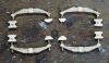
    If you're involved in mechanical engineering you'll know that 50% of all the things that get designed are brackets of some sort or another. The end of the sand pipes and the nozzles on the prototype are held in position by the mother of all brackets. It looks to me as if the originals are blacksmithed from 2" steel angle with another brackety plate bolted or riveted to the end, through which the sanding nozzle is connected to the valve (?) that combines the steam and the sand. There's no way around this other than making a lot of very small parts. Here they are...
    sand gear 4.jpg
    Only showing 5 out of 6 sets because the first trial set is already fitted. The angle brackets are made from 1mm x 1mm milled brass angle, bent and filed to a slight taper on one leg.

    The flat parts that look like the end of hockey sticks were marked on some scrap 0.5mm etch fret and cut out by piercing saw (see, I don't do it all by machine tool!). They're thicker than prototype but we need a bit of robustness in the model here.

    The longer turned parts are the nozzles, and, yes there is a hole in the end. Not that it'll be noticeable on the model, but it keeps me amused.

    The smaller turned parts are the body of the combining valve thingy. In reality it's a more complex shape than this because it brings the steam pipe into the sanding pipe at an acute angle, but I couldn't figure out how to make it easily. As you'll see in the assembled sanding gear a certain amount of cheating goes on.

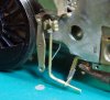
    The angle bracket is fixed inside the main chassis plate below the spring hanger. The small space for this on the prototype is mercifully also present on the model.

    sand gear 5.jpg

    To assemble and solder together tiny parts like this you really need them to fit together mechanically. There's no chance of holding them in position accurately while the soldering iron is applied if they just touch end to end. So the spigot on the back of the nozzle fits through the hole in the hockey stick and into a hole in the combining valve. The 0.9mm wire sand pipe fits into a hole in the combining valve and a hole in the sand trap casting. and the sand trap casting is spigotted into a hole in the underside of the sand box. Makes a difficult job...slightly less difficult.
    sand gear 1.jpg
    Once the angle bracket is soldered to the chassis and the hockey stick, nozzle and combining valve soldered together there follows a whole lot of bending and tweaking to get the nozzle exactly where it should be between wheels and track. There's no alternative to putting the wheels back in and sitting the chassis on track to check the nozzle position, then taking the wheels out to bend the bracket, then wheels back in and so on.
    sand gear 3.jpg
    The nozzle has to be positioned so that it does not contact tyre or rail at practical suspension positions, and the bracket has to be sufficiently clear of the inside of the tyre not to contact at maximum side play. Eventually it all comes good. The steam pipe is 0.4mm copper wire simply soldered to the back of the combining valve, not quite prototypical but in practice you can't see that on the model.

    Sand trap castings are not provided in the kit. That's bit of a surprise because other equally tiny cast parts are provided. Only the rear most sand boxes are outside the frames so it's only on those two sand boxes that you can see the sand traps. Bit of a head scratcher how to make these small and complex parts. I was ordering a few bits and bobs from Ragstone Models Ragstone Models and just asked if he knew of any castings for these parts because they're not in his catalogue (or anybody else's so far as I can tell). Magically when my order arrived what should fall out of the jiffy bag but a little packet containing 4 sand trap castings, and I hadn't even ordered them! Which reminds me, I owe Mr Ragstone £2-00 for them, which seems a very small amount to pay to save a lot of work. Ragstone be praised!

    You'll notice the missing brake blocks (won't you?). I've chosen to model up some for Mr Modelu to print. That way I can have them close to the tyres without an electrical short if they happen to touch. Some day they'll turn up along with the crew.

    Here it is all gloomy and arty in the Gifford style. Can't wait to get to the painting and weathering down here in the crud and the murk.
    sand gear 3-2.jpg

    I've just got five more to do now, and that'll keep me out of mischief for another week.
     

    Attachments

    • sand gear 2.jpg
      sand gear 2.jpg
      142.4 KB · Views: 3
    Diversion - making parts to make tools to make parts to make models
  • Ian_C

    Western Thunderer
    For years I've done small work in the jaws of a toolmaker's clamp held in the jaws of a small bench vice. That works pretty well, but the scope for positioning the work is limited, and some times you just can't get it to a convenient angle. I remember reading about instrument maker's vices in MRJ, Barry Norman I think. You see the odd one on eBay, usually made by Eclipse. I finally got around to making one of my own. It's based on a set of drawings and a casting from Hemingway Kits but modified to take my faithful and familiar toolmaker's clamp. It's a lathe and milling machine job but with a few changes you could make it on a lathe only I guess. Nothing too difficult. Here are the parts all machined from the iron casting and bar stock...
    parts 1.jpg

    And here's the finished article with all the bright work chemically blacked and the casting filled and painted. ..
    vice 1.jpg
    vice 2.jpg
    By loosening the big hand grippy knob the stem can be extended or retracted and rotated in two planes to position the toolmaker's clamp. Tightening the knob locks it all in position. Not shown, there's a clamp to clamp it to the edge of the workbench. That wasn't part of the Hemingway kit, just made up from odds and ends plus the clamp screw and swivel from a poundshop G clamp. I have it in mind to make alternative ends for the stem for different jobs.

    Learning from this project; drilling hard things. One advantage of using a decent quality toolmaker's clamp is that it will have hardened jaws. My old clamp was bought from RS Components a long time ago, it's 'Made in England' for heaven's sake, and the jaws are super hard. Pretty much file and saw proof. I needed to drill through part of it for the two mounting screws. I'd assumed that a HSS drill bit would find its way through with a bit of encouragement. No chance! The clamp is way harder than any HSS tool. Totally rounded drill bit and hardly a dimple in the clamp. That was a surprise. Some head scratching before I remembered I had a solid carbide stub drill. Thought I'd risk it, though it would be a shame to ruin the carbide drill. It drilled through the hardened clamp body with no problem, and no sign of wear on the drill cutting edges. Remarkable. Rock, paper, scissors etc...but tungsten carbide beats all.

    Maybe I can get back to building the 8F now?
     
    Top