No work has been done on the WD since the last post. If you like you can stop reading now. A lot of other vaguely related stuff has happened. Time was obviously invented to prevent everything happening at once but it doesn't seem to have worked.
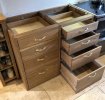
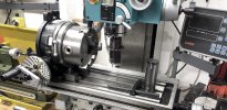
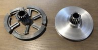
My conscience gradually got the better of me and I was feeling obliged to build the next stage of the long running fitted kitchen saga (ten years and running). Having sacrificed some modelling time to design some kitchen I realised that it would be a good idea to replace the planer thicknesses blades before processing a load more sawn oak. Changing and setting the blades was an afternoon's work once the new blades arrived, but when I set the machine up to try them out I found that the thicknesser feed was making an unusual noise. On removing the cover from the feed mechanism I found that one of the drive pulleys had disintegrated. The machine has a most Heath Robinson arrangement of flat belts, V-belts, gears and chain sprockets to take a drive off the end of the cutter block shaft and reduce the speed to drive the feed rollers, almost as if the designer had set out to use something from every page of the industrial drive components catalogue on his desk. Damn - need a spare pulley. Unfortunately Scheppach stopped making the machine years ago and by now there are few spares available. There's no way I'm scrapping the whole machine for that so I had to make a replacement pulley from scratch. Of course that turned into a performance since the V-belt on one part of the pulley was an odd section and I couldn't buy an off the shelf gear for the other part. I'd been intending to get a proper rotary table / indexing head for the milling machine for ages, and the need to cut a gear was the clincher. Gear type identified, involute gear cutter ordered and crash course in gear cutting followed. The original pulley was a low quality die casting, so badly aged that you could break it into pieces by hand. The new gear was cut from mild steel bar. The V-belt pulley was turned from a slice of extruded aluminium round bar. The two were a transition fit with some Loctite retainer. Works beautifully.
However, no return to kitchen design or even modelling. Some years ago we bought a couple of Velux window kits to add some natural light to the smaller upstairs rooms. One was installed a few years ago when the extension was built, the other window kit has sat taking up a load of space at the end of the workshop ever since. After a rough winter we thought it would be a good idea to have one of the more weather beaten roof pitches stripped and re-tiled, and at the same time have the Velux fitted. Quick job you'd think. Builder said two days, then didn't turn up on the day. The roof was fine in the end but the hole in the ceiling for the Velux must have been made with a bazooka. Tidiness isn't a thing with some tradesmen. The real purpose of the Velux was to have natural light over the modelling bench (your persistence has been rewarded, there is a modelling connection). It's always been a gloomy corner and suffered from damp some time back when the roof valley got blocked with autumn leaves. So it seemed like an opportunity to sort out that corner of the room. With old houses decorating work turns into minor building work which then escalates as you peel back the layers.
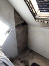
Hole around Velux tidied up and expanding foam fired enthusiastically into the messy voids. Many spiders made homeless. Crumbly plaster on adjoining wall stripped off. And, as we find occasionally in this house, a couple of bricks were made of oak. Presumably they were incorporated in the wall originally to provide fixing points for something. Often the wood is rotten. In this case damp from the leaky roof valley finished it off. A suitably sized antique brick and a half from the garden was mortared in.
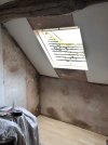
Reveals constructed around Velux and plastering completed. Scabby lining paper over the lath and plaster ceiling was removed and the ceiling sanded and skimmed. New lining paper going back on. At this point I'm contemplating taking down all of the lath and plaster ceiling and replacing it with Thermaline insulated plasterboard, but I come to my senses and don't escalate further. Also thinking that the old laminate flooring should be replaced while the room is in a state of chaos. Come to my senses again. Just finish what I started otherwise it'll be endless.
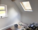
And about 10 litres of white emulsion finished the job. Ended up painting the whole room though. Still got blinds to fit. Amazing the difference natural light makes to a room. It's a lovely space now and I can move the modelling bench back into the corner soon. Looking forward to getting on with the WD again...except...
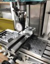
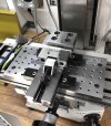
...there's another half done job that got interrupted by the builders and I need to finish that off to get the workshop back into a useable state. I bought a 100mm precision vice a while ago to replace the Indian 'value' vice that I usually use on the milling machine. It was OK - ish - but every time it was taken off and replaced it had to be indicated back in, and it was itself a bit geometrically challenged. It made precision work difficult and time consuming. The mill is trammed very carefully to the travel but the bed isn't exactly a level playing field. I made a fixture plate out of 15mm thick 275 grade steel plate and fly cut it in situ so I know the surface of the plate is perpendicular to the spindle axis. It's plain structural steel plate so it starts off with a mill scale surface and isn't particularly flat. Also since it's a rolled product and not normalised it has an amount of residual stress which is released when the surface is machined off. I took off the mill scale surfaces with a carbide face mill and then made a couple of passes on each side with the fly cutter to level out the curvature. 74 M8 holes were drilled and tapped (by hand!) at 25mm centres for fixturing. When it was bolted in place on the machine bed a final finishing pass was taken to get a perfectly flat surface.The plate was dowelled to the machine bed so it can be removed and replaced in exactly the same position. The vice has key slots on the underside and these can be used to key the vice to the fixture plate. A couple of steel keys were made to fit precisely in the slots (and yes, that had to be done on the 'value' vice, very , very carefully). The matching key slots were then milled into the fixture plate. Before I milled the key slots in the fixture plate I took a diversion and stripped the table and saddle assembly, cleaned everything, adjusted the lead screw backlash and re-fitted and adjusted the gibs. In theory when the vice is clamped to the fixture plate it'll be absolutely true to the X and Y axes and level in the X-Y plane. As it turned out the vice is good to within about 0.005mm in X, Y and X-Y across the width of the vice. I'm now able to reference the workpiece directly off the vice and not have to indicate the work after every move. Better quality work and much time saved. Very happy with that and about as good as it'll get on a machine like this.
The learning is that you can do precision work on even a low cost Chinese hobby milling machine if...
- You're prepared to completely strip and rebuild the machine before you use it.
- You can do enough measuring to find the machine's geometrical errors and work out how to correct them.
- You're prepared to invest some time, effort and money in setting up and workholding.
And after all that I still have to make kitchen part 2, although I'll probably time share that work with the WD. So maybe I'll post something model raiwayish here soon.
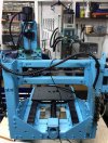
But hang on...I've just ordered a load of parts to make a bench top CNC milling machine...


