V2 4 wheel parcel van1/32 and G3

ChrisBr

Western Thunderer
Graham as I am closing in on the assembly of the frames it just occurred to me that the leaf springs appear to be threaded through all the frame angles. In the event of a spring break how would the spring be removed and replaced?
Michael
Michael,

Are you referring to the buffing spring horizontally behind the headstock or the bearing springs vertically holding the axleboxes in place?

Chris
 

ChrisBr

Western Thunderer
I would ask more, what is stopping it falling down, apart from the brake gear??

It seems to sit under the longitudinal as this angles to the headstock and also the angled beam connecting the headstock to the trimmer and longitudinal, all of which I would expect - what is not shown is that both beams are likely to have cutouts to accommodate the spring, as shown in the side view below...

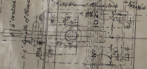
On a contemporary open wagon, with which I am more familiar, there are two horizontal bars running from the inside of the headstock to the far side of the trimmer which are bolted to both and which prevent downward movement, but also access when required, as seen in these snips from the relevant drawiing.

Screenshot 2024-04-30 220601.pngScreenshot 2024-04-30 220654.png

The answer to what stops it falling out is of course the through drawbar connecting the springs at either end. Again, based on later open wagon practise, this may well have passed through a hole in the Transomes, or a plated slot, which would have prevented it falling off and effectively held the whole assembly level.

Hope that helps.

Chris
 

michael mott

Western Thunderer
I am going to guess that the slots are plated otherwise the geometry would not allow installation after the frame is riveted together. Thanks for the additional information Chris.
Michael
 

Dog Star

Western Thunderer
I shall extract the referenced dwg. ( included in this topic) and take it wth me when I visit with Chris either later this week or early next when we can chew the cud and see if we can make a good fist of interpreting the dwg..

rgds, G
 

michael mott

Western Thunderer
Thinking some more about the spring issue, it would not be likely that the whole spring would need to be removed as one piece. The leaves (leafs) could be removed individualy so as long as the slot has enough clearance then even the longest spring ought to be able to be rotated through 90 degrees and then extracted.
Michael
 

michael mott

Western Thunderer
Yesterday I scrolled through 2 pages of NRM swindon drawings 568 lines of reference looking for a drawing in the date range from 1875-1876 and did not find any that appeared to reference the parcel van.

Michael
 

Pete_S

Active Member
Yesterday I scrolled through 2 pages of NRM swindon drawings 568 lines of reference looking for a drawing in the date range from 1875-1876 and did not find any that appeared to reference the parcel van.

Michael
All I could turf up was this:

OPC List:
Microfilm Card: 14375, Description: B Diagram of 4 wheel 21' passenger brake van L146 V2 GWR, Undated
(Probably a weight drawing though)

Pete S.
 

michael mott

Western Thunderer
All I could turf up was this:

OPC List:
Microfilm Card: 14375, Description: B Diagram of 4 wheel 21' passenger brake van L146 V2 GWR, Undated
(Probably a weight drawing though)

Pete S.
Pete I believe the drawing that you referenced is the one in Russell’s book it does not show any details of the frame. Today I scrolled through a photo stream at NRM of Swindon drawings and checked every drawing that illustrates the traverse leaf springs. None of the drawings that are close to the 1876 date show any detail of the frame regarding the removal of the spring. Given that the coupling hook appears to be attached to the spring in a number of ways depending on the drawing, once the coupling has been removed, the spring could be rotated as a unit but the slot in the frame would need taller which would weaken the frame angles. If the spring could be assembled in situ everything would be much easier. However I understand Graham’s comment regarding the central rivet.
Michael
 
Last edited:

Pete_S

Active Member
Pete I believe the drawing that you referenced is the one in Russell’s book it does not show any details of the frame. Today I scrolled through a photo stream at NRM of Swindon drawings and checked every drawing that illustrates the traverse leaf springs. None of the drawings that are close to the 1876 date show any detail of the frame regarding the removal of the spring. Given that the coupling hook appears to be attached to the spring in a number of ways depending on the drawing, once the coupling has been removed, the spring could be rotated as a unit but the slot in the frame would need taller which would weaken the frame angles. If the spring could be assembled in situ everything would be much easier. However I understand Graham’s comment regarding the central rivet.
Michael
I was present (i.e a spare pair of hands) when one of 933's springs was removed & I've been racking my brains to recall how it was achieved.

For certain, the racking plate on top of the frame had been removed (mostly rust anyway) & there was much ado with a car scissor jack (Mini Traveller), pinch bar & a certain amount of industrial language. All done after hours to avoid distressing the management.

Looking at the underframe pdf I posted a while back I *think* the sequence was this...

1: Tie spring to underframe with orange nylon rope.
2: Place jack behind spring (as far as possible) & compress the spring so it flattened sufficiently to be able to knock out the pin connecting it to the drawhook.
3: Gently release the pressure & let the spring relax (all the while praying it wouldn't escape & leap upwards like a 5ft steel salmon).
4: Remove the forked support bracket I mentioned earlier.
5: Release rope & lower spring to the deck.
6: Wash up & Go to the pub.

I'd imagine that the Works would have had a proper spring compressor that would tuck up behind the spring & bear on the headstock.

Pete S.
 

michael mott

Western Thunderer
Lots of jewelers saw work and tired fingers, w iron and hangers cut from .040 and .020inch respectively
IMG_2358.jpeg
IMG_2360.jpeg
All the brackets drilled. The plates for the spring hangers cut from some of the cutouts from the W irons.
Still to cut and bend the brake shoe hangers and clasp lever plates and posts. A never ending amount of bits it seems.
Michael
 

michael mott

Western Thunderer
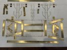
A number of items that have been made before the frames can be assembled include the clasp lever posts, the brake shoe hanger brackets and the footboard support brackets last but not least are the spring hanger brackets. The footboard supports are made from 3 pieces which still need to be soldered together.
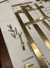
IMG_2365.jpeg

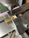
Next were the clasp lever posts which are a combination of some .093” tube flattened such that all the flatting is on one side. A fiddle of a set up without a proper press. This part married to the bottom part machined out of some .125 rod with a 00x90 thread to hold the levers and brace on the bottom.
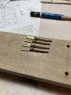
IMG_2366.jpeg
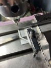
I had to narrow down some tiny toolmakers clamps to hold the top in order to drill the 2 holes.
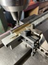
IMG_2367.jpeg
The spring hanger brackets have been challenging first the lower flattened part had to be sorted, a few tests gave me the dimensions that were needed the next picture shows the baldish end of the rods that were turned down out of some .125 rod they were the annealed
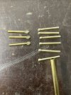
IMG_2372.jpeg
Those on the left have been squeezed in the large mill vice
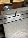
IMG_2374.jpeg
Then annealed again and bent. I had to resend them all so more annealing was undertaken I had to make half a dozen extra because some of them snapped right at the squeezed part. Once they were all bent the next task was to drill the hole in the flat part. A simple wood jig was made that clamped the long part and some scrap brass used to support the flat for drilling .072”IMG_2376.jpeg
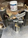
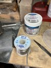
Finally the square back plate and the bent parts were soldered together using the third hand and some high temperature soft solder some worthington 97/3 with a water soluble flux.
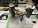
IMG_2378.jpeg

IMG_2380.jpeg

IMG_2381.jpeg
So this is the current state of play once all the hangers are soldered together I will drill the holes in the back plates.
Michael
 

michael mott

Western Thunderer
Thanks Simon, a sigh of satisfaction today when the spring hangers were all soldered together and the mounting holes were drilled into the W irons and then test fitted to the sole bars. My #1 eyeball drilling of the through the stick on labels that I had used to cut them out with the jewelers saw proved to be adequate as the 1/32 copper rivets located them without any issues. I am a happy camper this afternoon.
IMG_2386.jpeg


IMG_2390.jpeg
IMG_2388.jpeg
Time for tea.
Michael
PS smoke from wildfires northwest of Edmonton was causing an 11 on a scale of 10 yesterday and it was 10 this morning it has eased off a bit this afternoon but it is unpleasant to say the least.
 

michael mott

Western Thunderer
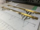
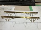
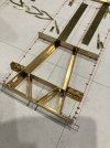
If assembling these parts were from a kit that had been designed and produced by someone else I would have been very cross with their accuracy
IMG_2399.jpeg
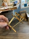
As it was frustrating for sure and I ended up having to remove rivets and redrill holes and re-rivet a couple of times. So very cross with myself for not being more accurate either the parts. Learning the hard way about cumulative errors.
IMG_2401.jpeg
That said it is taking shape. Warts an all!
Michael
 

Jon Nazareth

Western Thunderer
If assembling these parts were from a kit that had been designed and produced by someone else I would have been very cross with their accuracy
View attachment 215608
As it was frustrating for sure and I ended up having to remove rivets and redrill holes and re-rivet a couple of times. So very cross with myself for not being more accurate either the parts. Learning the hard way about cumulative errors.
View attachment 215609
That said it is taking shape. Warts an all!
Michael
It’s taking shape marvellously, Michael.

Jon
 

michael mott

Western Thunderer
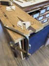
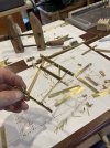
Thanks Jon, the plus for me is sorting out some new ideas about how to make some things. One thing I have been thinking about is some form of 2D sort of assembly tool similar to the loco frame building ones. Some type of miniature adjustable riveting dolly that will allow for holding a complex structure and still be able to hold it all steady then have the ability to set a rivet. Holding and riveting some pieces has been rather challenging and not ideal.
Michael
 
Top