The Heybridge Railway, 1889 to 1913

Ground frame New

RichardG

Western Thunderer
DSC_1145.jpeg
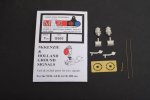
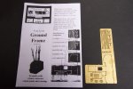
I bought this kit a few years ago. If it included some wire to make the details then this is lost. I have an etch and instructions.

DSC_1147.jpeg
With two true right-angles folded into the etch, the fourth side does not line up. The external corners on the top do not meet up either.
DSC_1149.jpeg
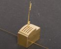
I broke off the fourth side and put it back in the right place, and added scraps of wire to build up the wonky corners. So there are seven parts in the frame here, not two as the designer intended.
DSC_1154.jpeg
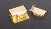
Then I realised the levers are rather intricate to assemble. A two-lever frame will be correct for the location on my layout, and I certainly don’t want to make two levers with no purpose.

So I cut the model into two pieces to turn it into a two-lever frame. It would be daft to try to re-use the second side because it didn’t fit properly the first time round. So I added a new side oversize and trimmed it later.

DSC_1155.jpeg
It will be wise to make the levers movable in case of inquisite fingers. I can solder them both onto the pivot rod, or maybe squeeze in a spring or some pvc tubing between them after painting.

DSC_1163.jpeg
So, a simplified model. I have my doubts about the longevity of the levers. Nickel silver would be stiffer.

DSC_1168.jpeg
The marks from the wandering drill bit will disappear after I lower this into the ground :rolleyes:.

There are just 15 parts in this model; eight from the kit and seven from me.
 
Point position indicator New

RichardG

Western Thunderer
DSC_1170.jpeg
I can include a point position indicator on the layout to help suggest the period being represented when no trains are in sight. This design by McKenzie and Holland rotates on a vertical spindle and was used by the nearby GER and other companies.

DSC_1176.jpeg
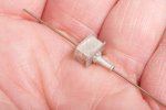
The first task is to drill a hole vertically through the base. This means a hole 0.75 mm diameter and 12.4 mm long, through a piece of white metal.

I find, if I hold the work in my fingers and start to feel it getting hot, this means the swarf is melting and forming a slippery coating on the bit. Stop and clean up and restart. I used Wahl clipper oil as the lubricant. I don’t think it really matters whether you use oil or silicone or just about any body fluid, just use something and keep on replenishing it.

DSC_1177.jpeg
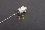
The 0.75 mm hole in the base is a clearance for this 0.7 mm wire which forms the spindle.

The lamp housing is missing its third lens, so I took a brass panel pin and turned down its head to make something which looked a bit like a lamp lens. I was so pleased with this so I removed the cast lump representing the second lens and worked up another pin to match.

DSC_1192.jpeg
The business of fitting this onto the layout and arranging its linkage to the associated point mechanism are for the future.
 
Last edited:

RichardG

Western Thunderer
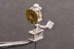
I have edited the last post because I put the balance lever in the wrong place. I have replaced the final photo.

There are just nine parts in this model; five from the kit and four from me. It does however look quite authentic when viewed from a normal distance.

DSC_1203.jpeg
Posed over a convenient hole in the baseboard.

Mangapps museum have one of these or something very similar, I might remember to take this model along on my next visit.
 
Top